Final Project Development
Your project should incorporate 2D and 3D design:
- additive and subtractive fabrication processes,
- electronics design and production,
- embedded microcontroller design, interfacing, and programming,
- system integration and packaging
Where possible, you should make rather than buy the parts of your project
Projects can be separate or joint, but need to show individual mastery of the skills, and be independently operable
✂️ Garment Pattern Cutting
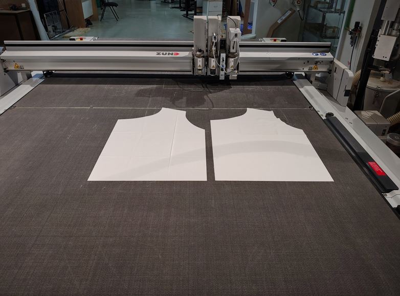
Before beginning the embroidery process, I first prepared all the fabric panels required for my waistcoat. Since I decided to fabricate the complete garment within the lab, the first step was to cut the fabric patterns to my measurements using the Zünd Digital Cutting Machine. Once the fabric pieces were accurately cut, they were embroidered using the Brother SE2000 embroidery machine and finally stitched together to form the finished garment.
Using a digital cutting machine significantly improves dimensional accuracy, repeatability, and cutting quality compared to manual cutting. It also reduces material waste and ensures that every pattern piece matches the original CAD design.
🛠 Digital Fabrication Workflow
The complete workflow for fabric cutting is shown below:
Fusion 360 (2D Pattern Design - DXF) → Zünd Cut Editor (CAM Preparation) → Cut Queue (Job Server) → Zünd Cut Center (Job Execution) → Zünd Digital Cutter
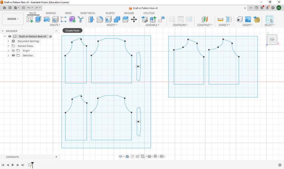
1️⃣ Creating the 2D Garment Pattern
The waistcoat pattern was first designed in CAD and exported as a DXF file. Each individual panel of the garment was prepared according to the required body dimensions before being imported into the Zünd software.
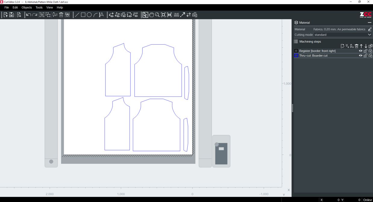
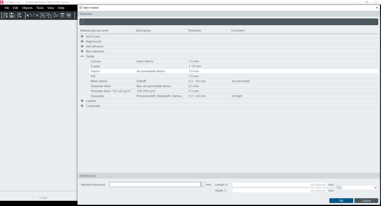
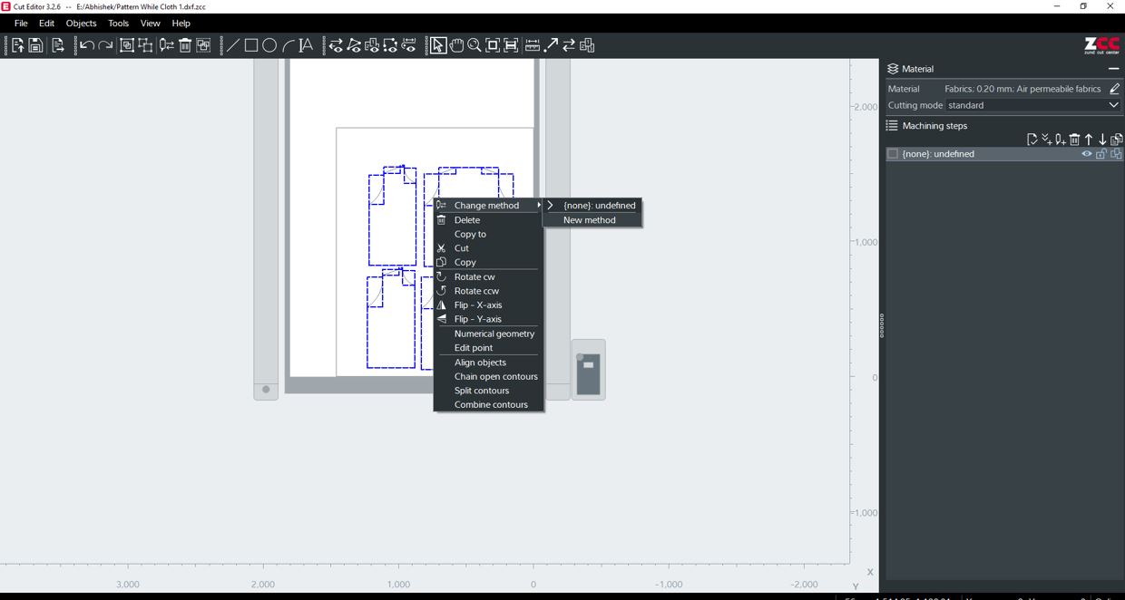
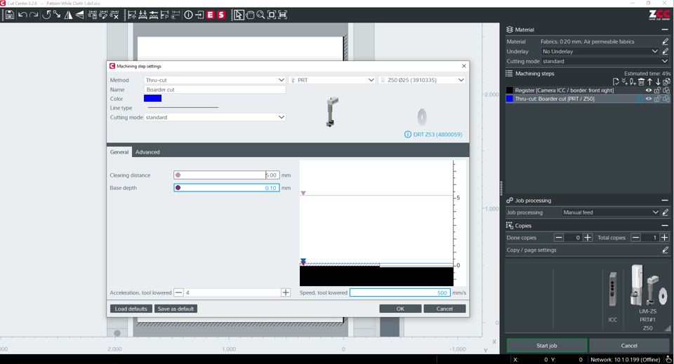
2️⃣ Preparing the CAM File in Cut Editor
The DXF file was imported into Zünd Cut Editor, where the cutting paths, tool selection, material parameters, and nesting layout were configured before sending the job to the cutting machine.
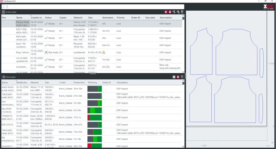
3️⃣ Sending the Job to Cut Center
After the CAM file was completed, it was transferred to Zünd Cut Center. This software manages the cutting queue, communicates with the machine, and executes the prepared toolpaths.
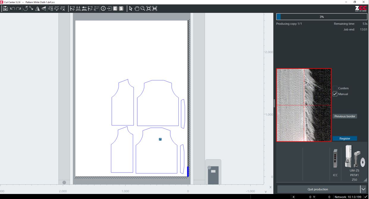
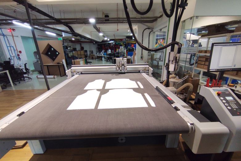
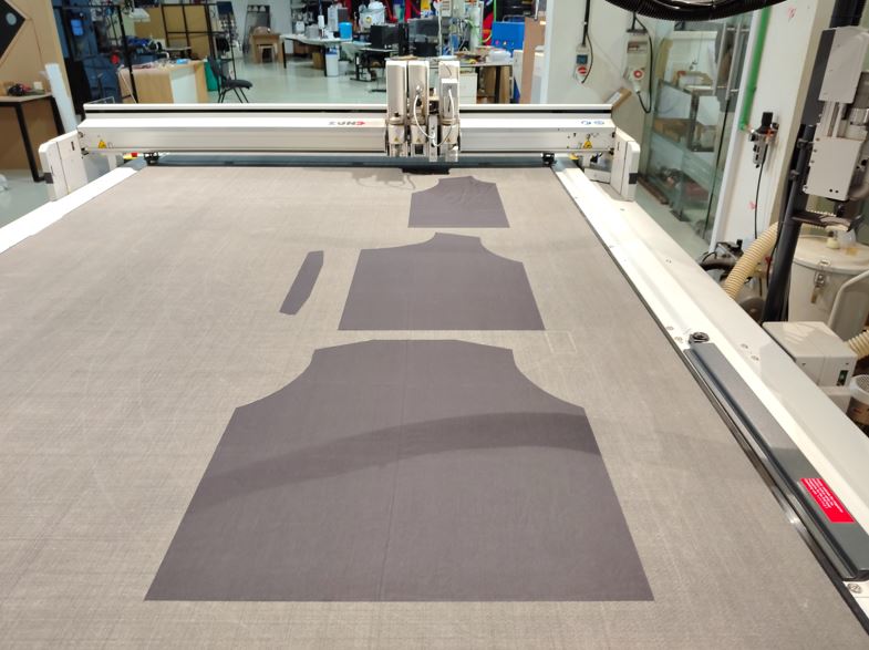
4️⃣ Cutting the Fabric on the Zünd Machine
The fabric was carefully placed on the vacuum cutting bed to prevent movement during machining. The oscillating rotary blade precisely followed the generated toolpaths, producing clean and accurate garment pieces ready for embroidery.
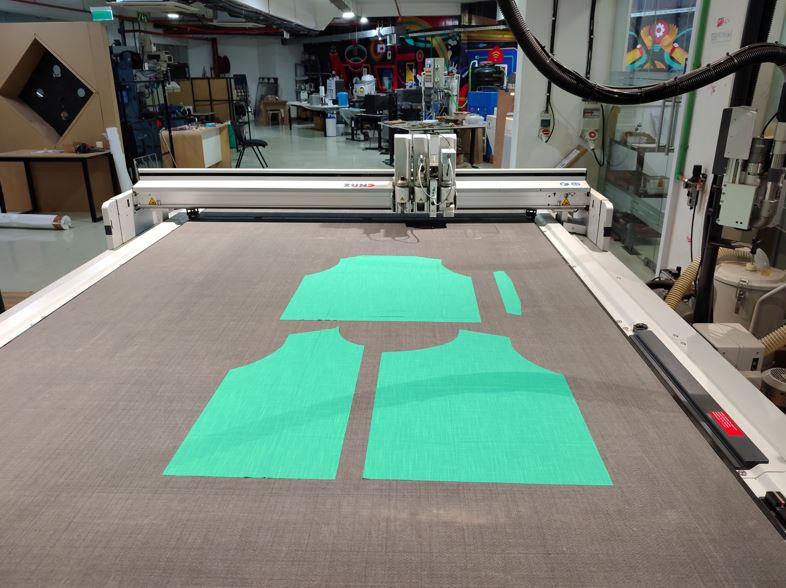
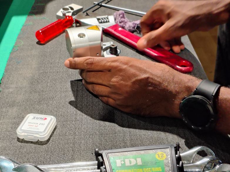
⚠️ What Went Wrong?
During cutting, the green cotton fabric was not completely cut through. Initially, the cutting depth was increased; however, the issue persisted. After further inspection, we compared the installed rotary blade with a new blade and found that the existing blade had become dull due to wear.
Since the cutting tool had lost its sharp edge, it was unable to fully penetrate the fabric despite increasing the cutting depth. Replacing the worn rotary blade restored the cutting quality and produced clean, complete cuts.
Electronic Design and Production
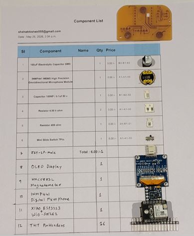
Main components of my project are:
- XIAO ESP32S3 Sense : Main Microcontroller Board
- Seeed Wio-SX1262 : LoRa module
- INMP441 : Digital Microphone
- HMC5883L : Magnetometer
- OLED Display Module
- Lipo Battery 3.7V 2200mAH
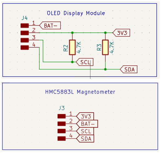
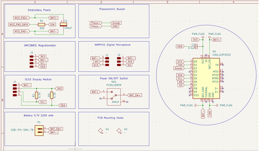
I used KiCAD to make schematic of my project, represented each module into a boxes for easy reference and debugging.
HMC5883L and OLED Display are 4-pin connection and they work on I2C communication thus I choose 4 pin through hole header to represent them in the schematics, and added 4.7K pull-up resistors between 3V3 and SCL, between 3V3 and SDA lines.
I2C Pull-up resistors
Here, make sure that the HMC5883L Magnetometer module and OLED Display display module does not have pull-up resistors on the module board, this can result in malfunction in I2C communication. To confirm this, we can use millimeter and check the SMD resistor value and it connection with 3V3 and SCL/SDA lines on the board final terminals.
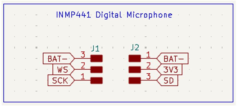
INMP441 DIgital Microphone this works on I2S (Inter-IC Sound) communication protocol specifically designed for transmitting digital audio data between chips.
How it works: Sound Waves --> Microphone --> Amplifier --> ADC (Analog to Digital Converter) --> I2S Output. Thus, Micro-controller receives digital data instead of analog voltage.
Below are it's pin signal explanation:
- SCK : Serial Clock (Microcontroller --> Microphone IC) at Every clock, it transfers one bit.
- WS : Word Select
- SD : Serial Data (Microphone --> Microcontroller) actual audio data.
- L/R : Generally connected to Ground
I don't have INMP441 module footprint, thus I decided to use two 3 pin through hole and then place then exactly apart as actual INMP441 module footprint.
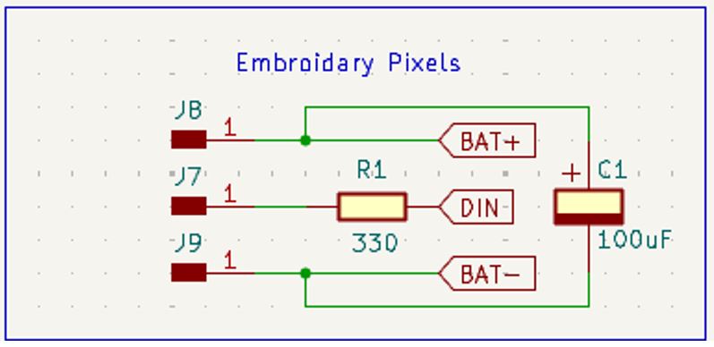
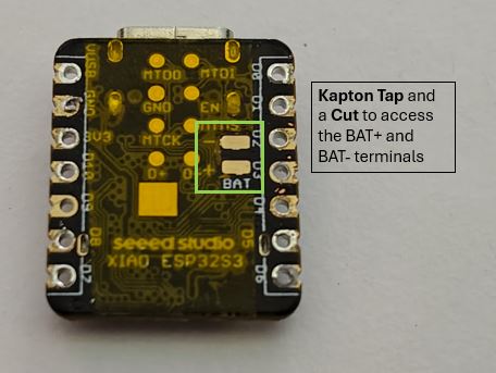
Embroidery Pixels, I used C1 100uF capacitor to avoid power line fluctuations when the 36 neopixels are turn on and off. The Neopixel strip is connected to BAT+ and GND instead of XIAO ESP32S3's 5V and GND because the XIAO may not able to supply 2.2 Amps of peak current to the Embroidery neopixels.
Additionally, I chose single pin SMD header and modified its footprint to match sweable snap's diameter, so that I can solder the male snap on the module PCB and stitch the final snap on the cloth.
XIAO ESP32S3 and Wio-SX1262
Credit: Saheen Pilayi :- It is important to keep in mind that we should not use GPIO08, GPIO09 and GPIO10 externally, because this pins are used by Wio-SX1262 internally via B2B connection for SPI SCk, SPI MISO, and SPI MOSI. Thus keep them reserved.
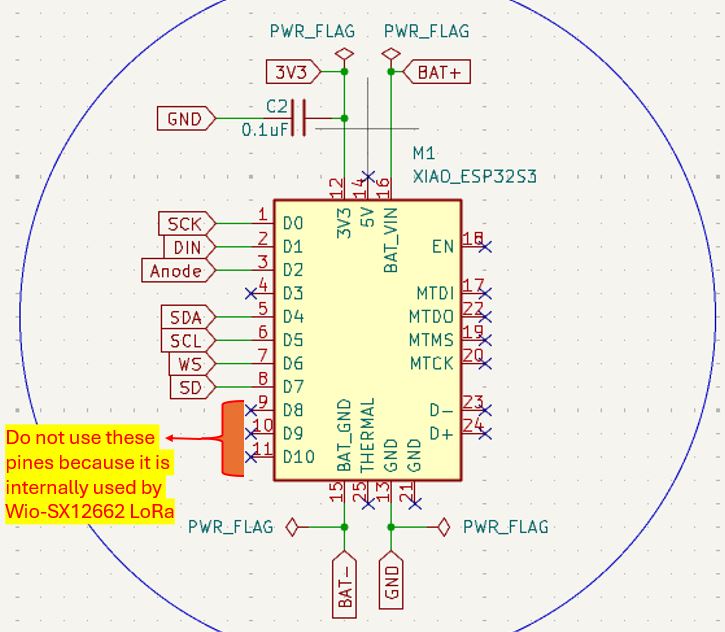
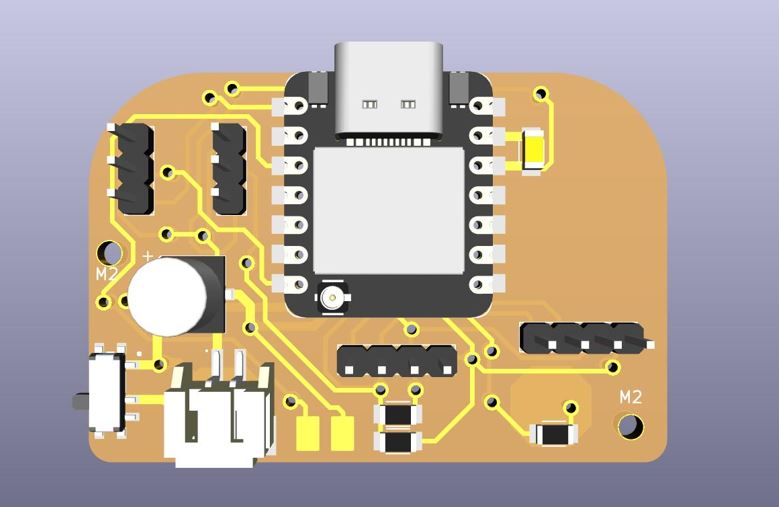
Schematics : Below shows entire schematic design, with all the sub modules and connection between them. it also includes the on-off slide-switch, piezoelectric buzzer, PCB mounting holes, and Battery connection.
What Went Wrong "BAT-" and "GND" labeling
Because "BAT-" and "GND" are at same potential (we cna get continuity between them), I used "BAT-" label after slide switch and for the ease of connection/routing mid-way of doing CKT layout I change few "GND" labels to "BAT-" label because of that the KiCAD did not show the connection between GND of Magnetometer and OLED Display (as they were changed to "BAT-" label) and thus were not connected to XIAO's "GND".
What I Learned "BAT-" and "GND" labeling
Always keep "BAT-" label between Battery and main on/off switch, after on/off switch use only "GND" Label by doing this we can avoid above mistake.
PCB Layout below are the main points that I learned and got from my instructor Saheen Palayi. These points shall be kept in mind while routing the Double layer PCB. These points helps in reducing the post production power-on issues, and makes debugging simpler and easy to identify the root cause.
What Went Wrong - My first routing and potential issues
- I keept vias inder XIAO ESP32S3
- I used both top layer and bottom layer to connect traces from XIAO.
- I used both top layer and bottom layer of same module for connecting traces.
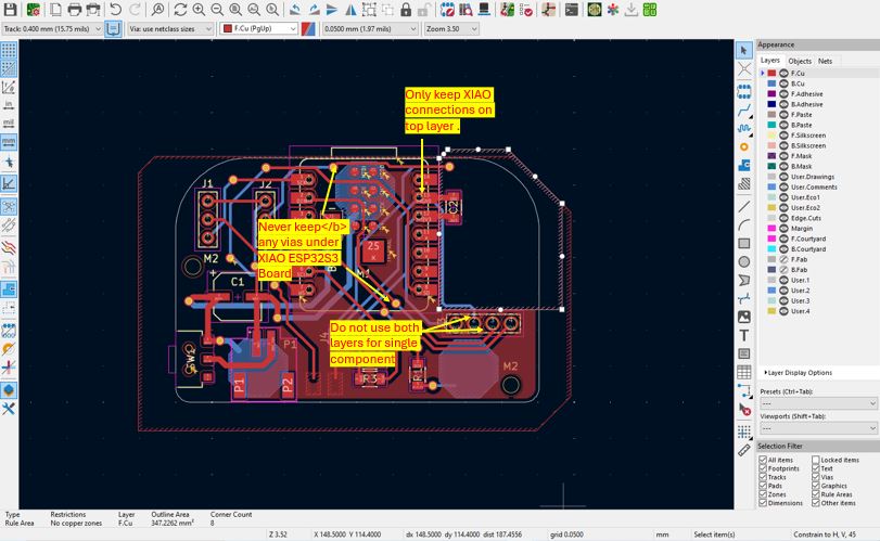
Double Layer PCB Routing Key Points
Below points applies when we solder XIAO board directly on the PCB like SMD components.
- Never keep any vias under XIAO ESP32S3 Board.
- Do not use the through hole of component mounting for via path as well. Keep vias and through holes separate.
- Never use both top and bottom both layers for soldering of single through hole module. (Always keep through hole connection for module either on top or on bottom any one layer. so this will avoid vias at the pin-header connection.)
- Ideally all through hole connections shall be on the bottom layer.
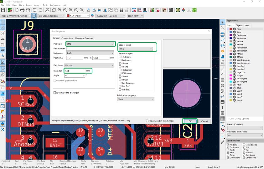
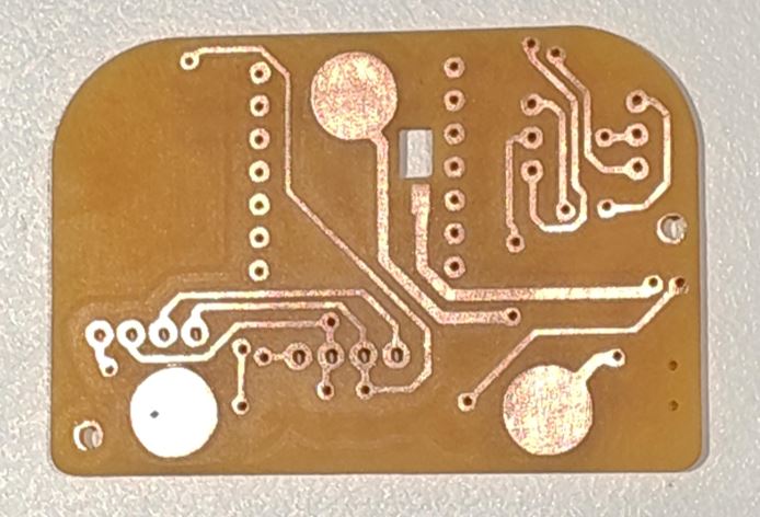
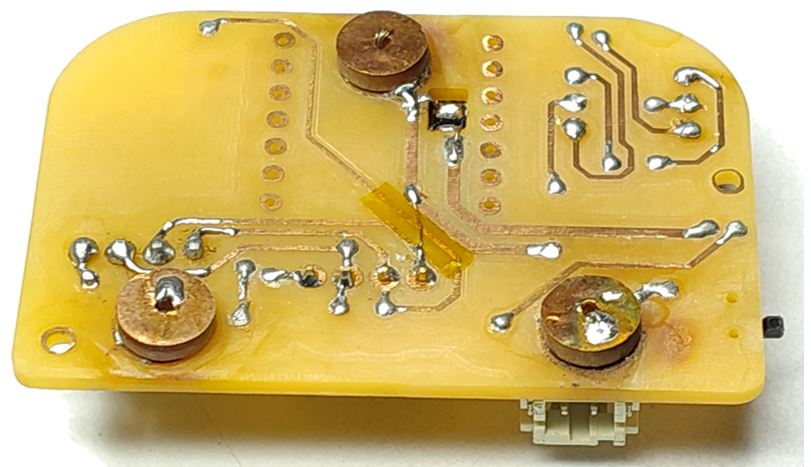
Circular Pads : I made custom circular pads for soldering snap buttons. so that my device can plug in to the waistcoat that I am stitching. To make this I used single through hole pinheader and modified its property to make a circular pad. Change the PAD type to SMD, Copper layer to B.Cu and Diameter as per Snap Button.
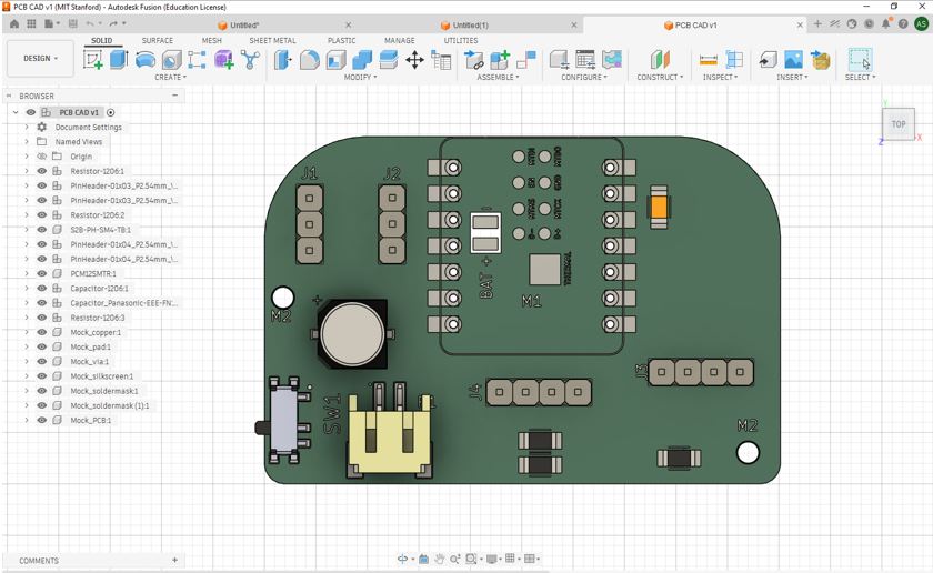
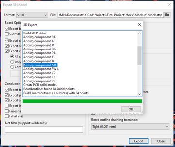
What Went Wrong - Adding XIAO ESP32S3 Sense 3D model
The 3D will perfectly appear in KiCAD rendering but it will not appear in the Step file that we download to import in Fusion 360.
Below we can see that the KiCAD 3D file is with XIAO ESP32S3
However, when I import it to Fusion 360 the XIAO ESP32S3 did not appear in CAD model.
This is because OpenCASCADE Error.
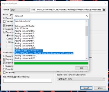
What I learnt - Convert the STEP file to a self-contained version
This is a known KiCad + OpenCASCADE bug with specific STEP files. The error means the XIAO STEP file has external references or linked sub-documents inside it that OpenCASCADE cannot resolve when copying into the export.
The Fix — Convert the STEP file to a self-contained version. The STEP file needs to be re-saved as a clean self-contained file.
In Fusion 360 --> Insert --> Import (Import the original XIAOEsp32S3v2.step) --> File --> Export --> Format: STEP (.step) --> Save as XIAO_fixed.step --> Then in KiCad --> Double-click M1 XIAO ESP32S3 --> 3D Models tab --> Replace the path with the new XIAO_fixed.step --> Re-export the board STEP -- Open in Fusion 360.
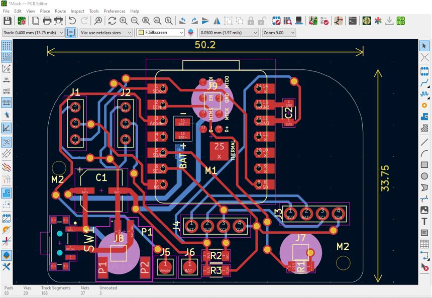
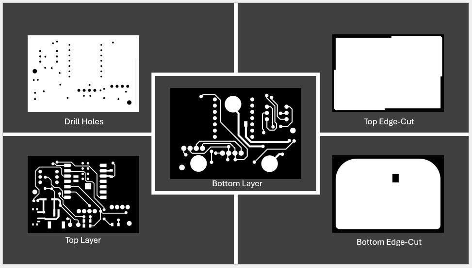
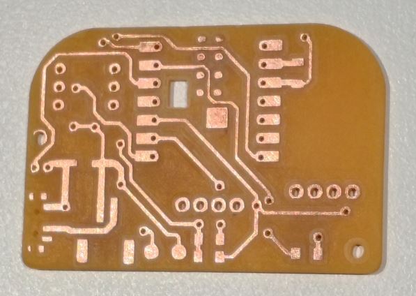
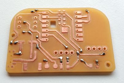
Below is my final layout and then generated Gerber files and Gerber to PNG and proceeded for PCB milling process.
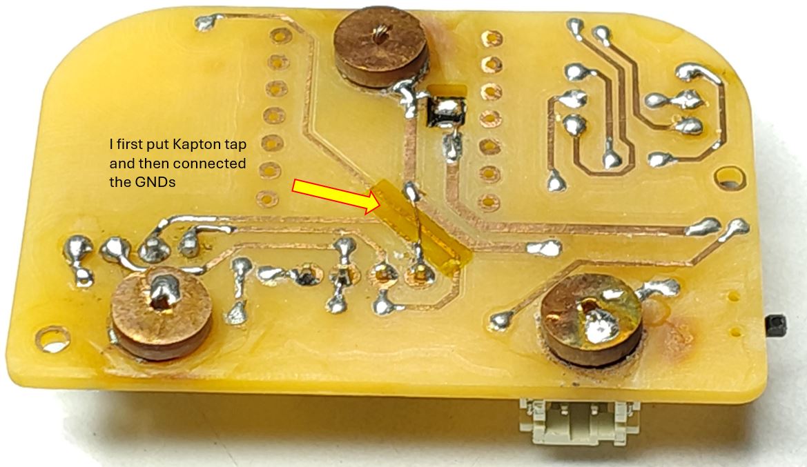
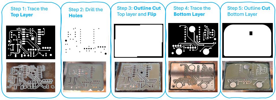
Double Layer PCB Milling
What I Learned :- copper pour --> eddy currents --> distorts magnetometer IC HMC5883L
Note : I removed copper pour because I am using magnetometer IC HMC5883L and copper pour can generate eddy currents that distort magnetic readings.
Also it it important to do not keep any copper high current traces underneath of magnetometer
To remove the copper pour, below are the steps that I followed, Credit Saheen Palayi
- First, I milled the traces with V-Bit for offset = 4 (Passes).
- Second, I changed the V-Bit with Drill bit and milled for offset = 28 (Passes). Here, technically we cna put offset = 0 but the calculation takes lot of time and mode CE gets stuck in calculation. Thus to optimize it I put 28 by trial and error.
- Third, again run the trace file to clear the copper pour.
- Fourth, then continued with same drill for milling holes and edge cut.
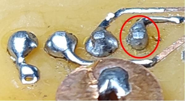
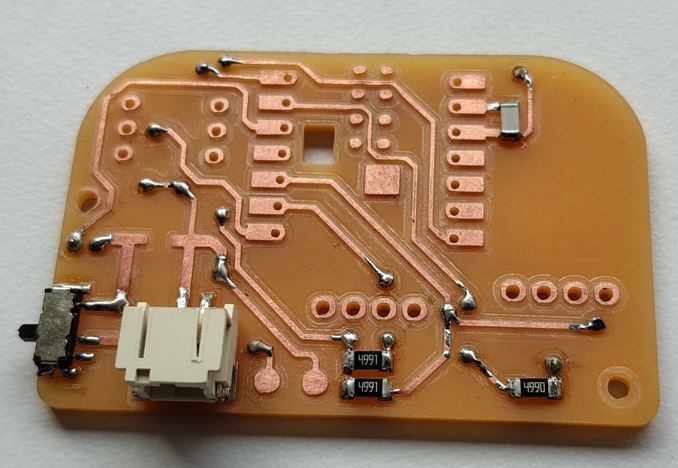
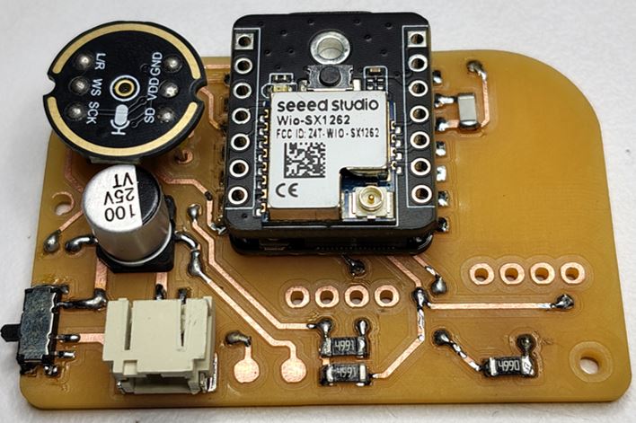
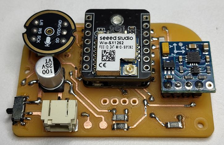
What Went Wrong :- I Started soldering, instead of making 3D model first
I started soldering INMP441, HMC5883L modules on to the milled PCB, instead of making 3D first. Because the 3D will decide the hight of the HMC5883L module on the main PCB. So that I can cut the module legs according to that high and solder it. Because of this I need to couple of time de-solder and again solder to get the desire hight through trial and error.
Due to this, a few through hole pads came out of its place and I need to use coper wire around it to fix it. And this caused a little hight of through hole terminals of HMC5883L modules compared to other through hole soldering.
What I Learned :-
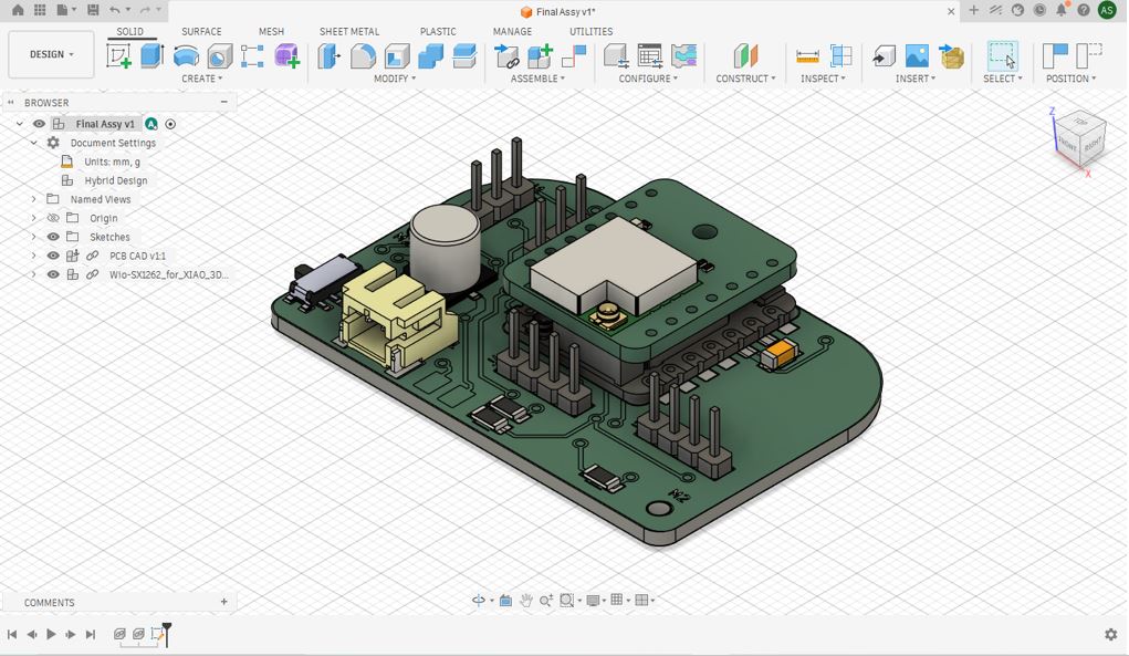
Always solder the PCB with the through hole module after making the confirmed 3D of entire module and encloser. Follow below steps.
- First, make 3D of encloser with the 3D of PCB along with plug-in modules.
- Then, Start BCB soldering with the confirmed high of through hole modules.
- This saves lot of de-soldering and soldering time. And prevents soldering mistakes and re-works.
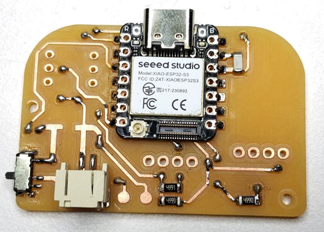
Soldering I started soldering the components and modules on to the milled PCB.
What I Learned - Debugging
1. I have two batteries, one is 2.9V and another is 3.8 V open circuit voltage. 2. When I connect the 3.8 V battery to my device and turn_on slide switch it gets connected with BAT+ and BAT- of XIAO ESP32S3, before turning on the slide switch the voltage at battery connector JST terminals is 3.8V and after turning on the Slide Switch the voltage at battery connector JST terminals is 0.4V. Now further when I connect XIAO ESP32S3 with USB the battery connector JST terminals is V 3. When I connect the 2.9 V battery to my device and turn_on slide switch it gets connected with BAT+ and BAT- of XIAO ESP32S3, before turning on the slide switch the voltage at battery connector JST terminals is 2.9V and after turning on the Slide Switch the voltage at battery connector JST terminals is 0.26V.Now further when I connect XIAO ESP32S3 with USB the battery connector JST terminals is 0.609V.4. I do have a DC power supply and multimeter and TP4056 module.
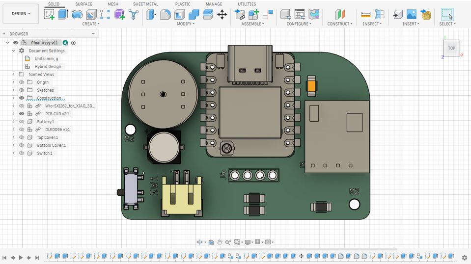
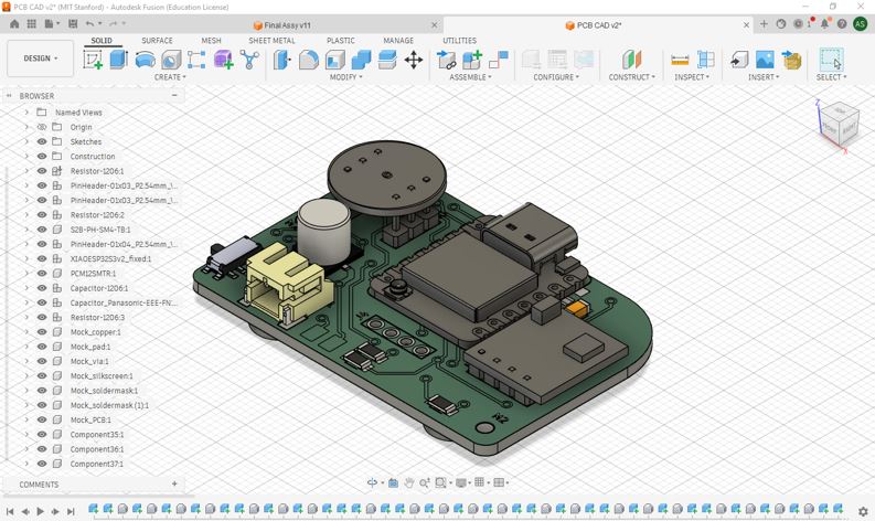
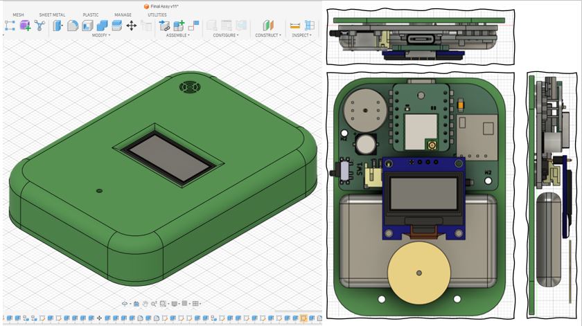
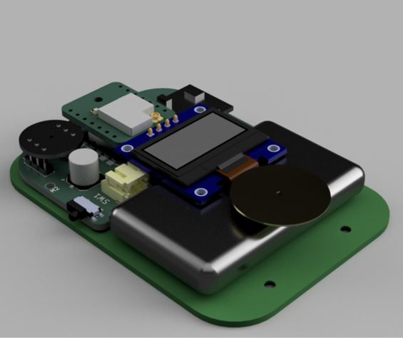
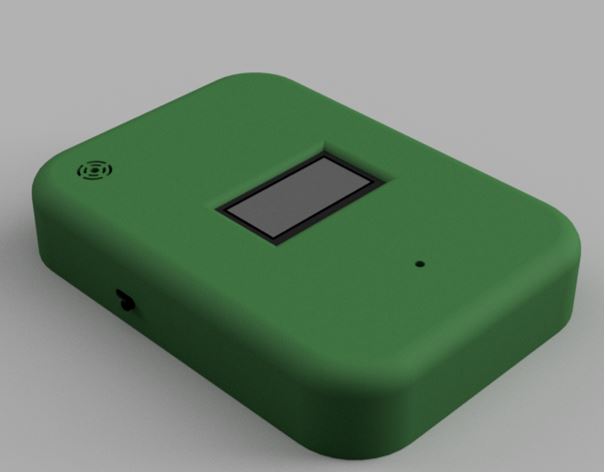
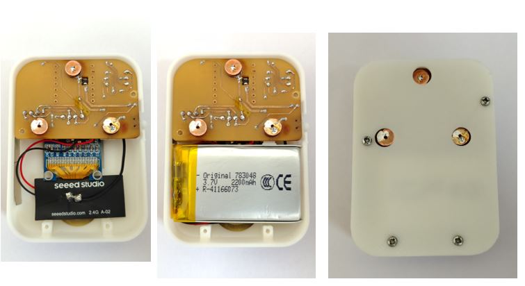
Enclosure Design
First, I imported the KiCAD PCB .step file into Fusion 360. Then I created 3D of INMP441 Digital Microphone and HMC5883L Magnetometer. The Step files of these modules were not available.
Embroidery Pixel Module
I decided to make Embroidery pixel module in the lab and then use it in the embroidery work. To do this, my instructor suggested to use Carvera PCB Machine because I can multiply the modules in the gerber to PNG layout and then mass-produce it with less wastage.
Digital Fabrication Process : KiCAD PCB Design --> Gerber to PNG (Layout for 40 Modules)--> Mods CE (Generate G-Code) --> Carvera Controller --> PCB Milling --> Soldering --> Testing on Jig --> Done!
KiCad PCB Design
First, I made the schematic design with WS2812B and used 0.1 uF capacitor across the positive and negative act as local energy storage.
Gerber to PNG (Layout for 40 Modules)
I used Layout option in Gerber2PNG to generate Layout for milling 40 Modules. As si was going to use Carvera Machine, I selected Generate for Carvera and then in Layout Setup, I entered 5 rows and 8 columns and downloaded the PNG. This steps need to be done for both TraceLayer and DrillLayer.
Mods CE (Generate G-COde)
Now, we need to open these PNG files of TraceLayer and DrillLayer into ModsCE to generate the G-code/Tool path for Carvera Machine.
When we start mods and load Carvera the default values are different . But after opening mods and clicking " load file " from the left side bar I added below file which will setup the defaults values that fits our machine, so that's e don't have to change it every time. CarveraMODSSV4.4.json
We can verify the Tool path using online NC Viewer or also in CARVERA CONTROLLER Software.
Carvera Controller
Carvera Controller Tool that we can install and use to connect with Carvera Machine wirelessly via wifi. The tool can be downloaded for here --> Carvera & Carvera Air Controller.
Below is its home screen and follow below Steps for setup.
- Step 1: Connect to wifi by clicking on "NA" button
- Step 2: Click "None" button and Select "Prob" : the machine will begin do Automatic calibration.
- Step 3: Click "Side Aero" button, a new screen will slide from the right, set the job origin using x+/x- and y+/y- buttons.
- Step 3: Click "Side Aero" button, a new screen will slide from the right, set the job origin using x+/x- and y+/y- buttons.
- Step 4: Click "Set Origin" Enter X-offset:0 and Y-offset:0, select "current pos"
- Step 5: Click "Config and Run" select Auto leveling enter x-points and y-points.
- Step 6: Click "Open" in the left bottom and open the G-code file.
- Step 7: Click "Upload & Select" and then "Run"
PCB Module Milling
PCB Module Fabrication
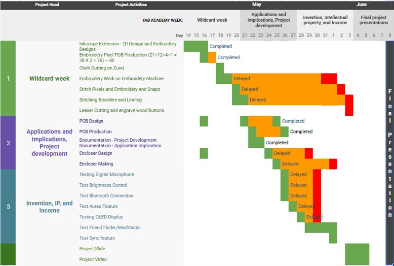
Tracking your progress at week 19 (29-May-2026)
What tasks have been completed, and what tasks remain?
Answer: So far, I have completed below listed tasks:
- 2D Design of Embroidery
- Embroidery Pixel Design and Production
- Main PCB design and Production
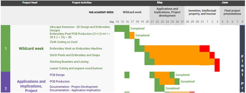
Below is the pending tasks:
- Firmware Development and Testing.
- Encloser Design
- Encloser Making
- Embroidery Machine work
- Stitching the Cloth
- Final Project Video
what's working? what's not?
Answer: Below list is for things that are completed until now:
- Embroidery Test worked well, need to reproduce
- Embroidery Pixel worked 38 out of 40 pixel module worked well
- The task time planning did work as anticipated
- PCB is not charging the 3.7 V Battery
what questions need to be resolved?
Answer:
- Firmware development and working
- Will Neopixel work well when stitched with conductive threads?
- Will Mobile App work well with the firmware?
what will happen when?
Answer: Below is my revised Planning:
- 29/05/2026 : Encloser Design and Critical Corners/Slide Switch Tests
- 30/05/2026 : Firmware Testing, Debugging
- 31/05/2026 : Final Project Documentation, Stitching Pixels
- 01/05/2026 : Encloser Production, remaining Embroidery work completion
- 02/06/2026 : Stitch all pixels with conductive threads
- 03/06/2026 : Stitching cloth borders
- 04/06/2026 : Final Testing
- 05/06/2026 : Slide and Video making
What have you learned?
Answer: Below are my learning while developing my final project
- PCB Design
- What went wrong: I missed to connect OLED GND and Magnetometer GND to the main GND of XIAO ESP32S3.
- Learning : Because I named some of the grounds as "BAT-" and some as "GND", I forger to connect both of them. teh "BAT-" shall be only until Slide switch and after that all shall be labeled as "GND"
- Embroidery Test Work:
- What went wrong: I was clamping the embroidery bed upside down, which was breaking the thread multiple time. And embroidery work was taking a lot of time.
- Learning: We accidentally used the marking frame to continued/match the previous embroidery work. When we realize the embroidery tray shall be flipped. After which the embroidery worked really well with comparatively less thread breaking.
- Embroidery Pixel Module
- Learning: The Pixel PCB diameter can be further reduced. Currently the dia is 14mm it can be reduced to 10mm. This is learning for my future development.
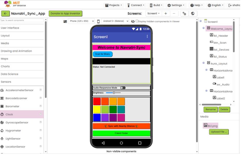
Mobile Application
I tried MIT App Inventor during my application week 15 and developed a primary version of my BLE Application. I decided to use that as my draft UI design and make a new prompt to design final version of my BLE based application using Claude Design.
Below, is my Application development Week - Android Application for reference.
Below, is a new prompt and detailed instruction that I defined make new version on reference of earlier version using Claude Design.
AI prompt:
Project name is “Rangbheru” Mobile App screens_needed are as below:
- Top Bar: BLE scan button - Connect / pair XIAO ESP32S3 Sence, show connected device name “Bheru A1”, I have two devices “Bheru A1” and Bheru A2”, and sliding button on the top right to toggle between bright (white/day) and dark (black/night) modes. Top Bar shall be common in all the screens.
- Screen for Color, Aura & brightness control and mobile apps shall communicate the values of Color; Aura, and Brightness level to device over BLE.
- Color picker style: HSV square + sliders, and the 12-step colors:
- Red #FF0000 Primary
- Red-Orange #FF4500 Tertiary
- Orange #FFA500 Secondary
- Yellow-Orange #FF8C00 Tertiary
- Yellow #FFFF00 Primary
- Yellow-Green #9ACD32 Tertiary
- Green #008000 Secondary
- Blue-Green #008B8B Tertiary
- Blue #0000FF Primary
- Blue-Purple #8A2BE2 Tertiary
- Purple #800080 Secondary
- Red-Purple #C71585 Tertiary
- Aura control shall have three Aure buttons in a single row
- First is slow blinking frequency with random colors, smooth color change of 36 neopixels
- Second is medium random blinking frequency with random colors and random turn on/off on 36 neopixels
- Third is fast random blinking frequency with random colors and random turn on/off on 36 neopixels
- Brightness: Slider control 0% - 100%
- Screen for Audio_viz : Audio reactive mode (visualizer + settings), Live waveform.
- Audio reactive mode as "Beat Sync" toggle button.
- Audio Sensitivity : Slider control 0% - 100%
- Screen for Mesh map and Friend finder - It shall have “Frind Finder” on/off slider, nearby nodes with bearing/distance, compass to nearest node, the app should use mobiles GPS data and send to device the device has Magnetometer module on it, so it can calculate direction and show on direction arrow OLED screen. Once two friends are in BLE range of each other -> Friend Sync: Two Friends can sync their color and blinking pattens of neopixel
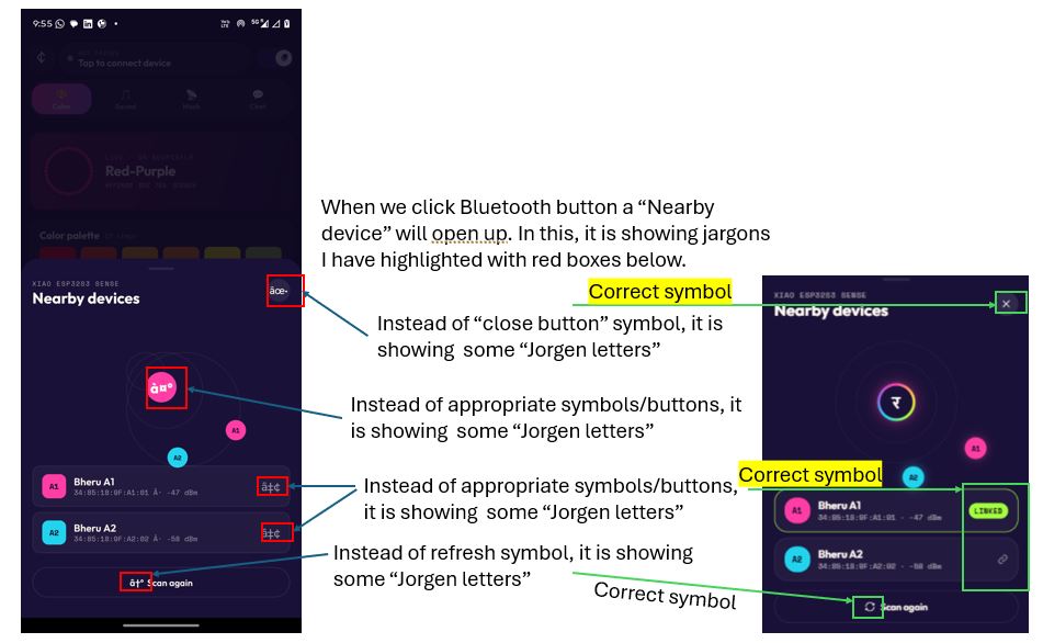
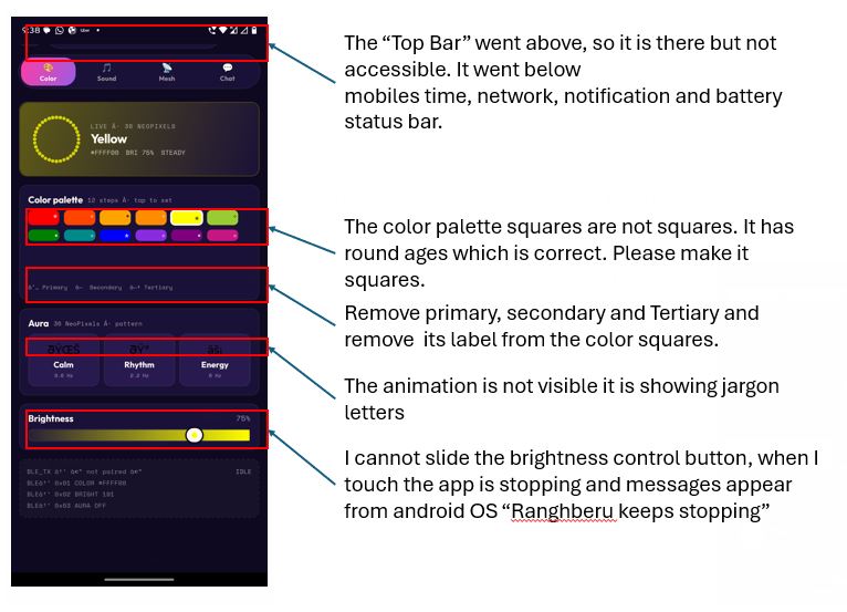
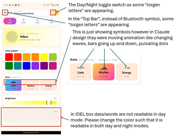
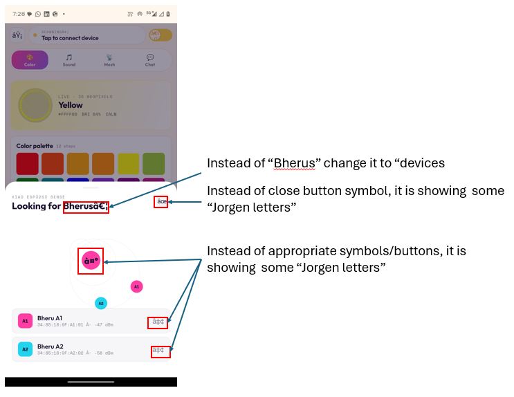
What Went Wrong - Icons and Animations didn't appear as rendered App
Below listed icons needed fix.
Firmware Development
First, I listed down all the features that I need to develop the Firmware. Secondly, the Hardware firmware has to work with mobile app thus I gave both requirement and feature list to Claude to have smooth interface programming between mobile App and hardware firmware.
AI prompt to Claude Code :
Feature 1: Bluetooth Connection and Device Pairing
Hardware Firmware:
- On power-up, the device shall enable Bluetooth (BLE) and display the message "Enable Bluetooth & Connect Bheru" on the OLED screen.
- The device name shall be "Bheru A1". I have two devices, "Bheru A1" and "Bheru A2". The device names will be defined in the firmware of each device.
- Once connected, the OLED shall display "Connected" for 5 seconds.
Mobile App - Screen 1:
- A Bluetooth icon shall be displayed in the top bar.
- When the user taps the Bluetooth icon, a translucent overlay shall appear showing a Bluetooth scanning animation and a list of available Bluetooth devices.
- Next to the Bluetooth icon, the currently connected device name shall be displayed (for example, "Bheru A1").
- I have two devices, "Bheru A1" and "Bheru A2". The device names will be defined in the firmware of each device.
- The connected device name shall be displayed in the top-right corner.
- This top bar shall be common across all screens in the application.
Feature 2: Color, Aura, and Brightness Control
Mobile App Screen:
- Color Picker Style: HSV square with sliders.
- Brightness control slider.
- 12-step color palette:
- Red (#FF0000) - Primary
- Red-Orange (#FF4500) - Tertiary
- Orange (#FFA500) - Secondary
- Yellow-Orange (#FF8C00) - Tertiary
- Yellow (#FFFF00) - Primary
- Yellow-Green (#9ACD32) - Tertiary
- Green (#008000) - Secondary
- Blue-Green (#008B8B) - Tertiary
- Blue (#0000FF) - Primary
- Blue-Purple (#8A2BE2) - Tertiary
- Purple (#800080) - Secondary
- Red-Purple (#C71585) - Tertiary
- Three Aura buttons in a single row:
- Aura 1: Slow blinking frequency with random colors and smooth color transitions across 36 NeoPixels.
- Aura 2: Medium blinking frequency with random colors and random on/off effects across 36 NeoPixels.
- Aura 3: Fast blinking frequency with random colors and random on/off effects across 36 NeoPixels.
- The mobile application shall transmit the selected color, Aura mode, and brightness level to the device over BLE.
Hardware Firmware:
- The device shall receive the color, Aura mode, and brightness level from the mobile application over BLE.
- The firmware shall control the 36 NeoPixels accordingly, including color, brightness, and blinking effects.
- The Aura patterns shall be implemented in the device firmware:
- Aura 1: Slow blinking frequency with random colors and smooth color transitions.
- Aura 2: Medium blinking frequency with random colors and random on/off effects.
- Aura 3: Fast blinking frequency with random colors and random on/off effects.
Feature 3: Audio Visualizer
Mobile App - Audio Visualizer Screen:
- Audio Reactive Mode (Visualizer + Settings).
- Live waveform display.
- Audio-reactive sensitivity slider.
- The mobile application shall send the Audio Reactive Mode status (ON/OFF) to the hardware over BLE whenever the status changes.
- The mobile application shall also send the sensitivity slider value to the hardware over BLE.
Hardware Firmware:
- The device shall receive the Audio Reactive Mode status and sensitivity value from the mobile application over BLE.
- An INMP441 digital microphone is connected to the XIAO ESP32S3 Sense. Please refer to the connection table above.
- The firmware shall process the microphone input and animate the 36 NeoPixels according to the detected audio waveform.
Feature 4: Mesh Map and Friend Finder
Mobile App Screen:
- Mesh map displaying nearby nodes with bearing and distance information.
- A Friend Finder ON/OFF slider.
- The mobile application shall send the Friend Finder status to the hardware over BLE.
Hardware Firmware:
- The firmware shall integrate Meshtastic, an open-source, off-grid, decentralized mesh network.
- The device shall receive the Friend Finder status from the mobile application over BLE.
- When enabled, the device shall discover nearby Meshtastic nodes and display their names.
- The device shall broadcast its own node name and GPS location data.
- When a user selects a nearby node, the OLED shall display the direction of that node.
- The user will hold the device like a compass.
- The device shall use magnetometer data to determine North/South orientation and calculate the direction to the selected node.
- When two friends are within BLE range of each other, a Friend Sync feature shall allow synchronization of NeoPixel colors and blinking patterns.
Feature 5: Mesh Chat
Mobile App - Chat Screen:
- Users shall be able to send and receive messages between mesh nodes.
- Two Meshtastic nodes shall be able to communicate directly using text messages over the mesh network.
/*
 * RangbheruFirmware.ino
 * XIAO ESP32S3 Sense + Wio-SX1262
 *
 * Libraries required (install via Arduino Library Manager):
 *   NimBLE-Arduino          by h2zero
 *   FastLED                 by Daniel Garcia   (>= 3.6.0, replaces Adafruit NeoPixel)
 *   Adafruit SSD1306        by Adafruit
 *   Adafruit GFX Library    by Adafruit
 *   arduinoFFT              by Enrique Condes
 *   RadioLib                by Jan Gromeš
 *
 * Board: XIAO_ESP32S3 (Seeed Studio XIAO ESP32S3)
 */

#include <Arduino.h>
#include <Wire.h>
#include <SPI.h>
#include <NimBLEDevice.h>
#include <FastLED.h>
#include <Adafruit_SSD1306.h>
#include <Adafruit_GFX.h>
#include <math.h>

// ─────────────────────────────────────────────────────────────────────────────
// FEATURE FLAGS  — set to true one-by-one as you test each module
// ─────────────────────────────────────────────────────────────────────────────
#define ENABLE_LORA    false   // set true later for A2 mesh testing
#define ENABLE_AUDIO   true    // Beat Sync audio reactive (INMP441 I2S mic)
#define ENABLE_MAG     false   // set true for compass / mesh test

#if ENABLE_AUDIO
  #include    // new ESP-IDF 5.x I2S API (avoids conflict with FastLED)
  #include
#endif

#if ENABLE_LORA
  #include
#endif

// ─────────────────────────────────────────────────────────────────────────────
// PIN DEFINES
// ─────────────────────────────────────────────────────────────────────────────
#define I2C_SDA          5     // D4
#define I2C_SCL          6     // D5
#define NEOPIXEL_PIN     2     // D1  (via 499Ω)
#define NEOPIXEL_COUNT   34    // 17 front + 17 back (waist)
#define LED_TYPE         WS2812B
#define COLOR_ORDER      GRB
#define MAX_MA           1500  // FastLED current cap (mA) — lower for thin conductive thread

// ── Ring layout (0-based FastLED indices) ────────────────────────────────────
// Front: outer circle first in chain → inner → center
#define FRONT_OUTER_START  0
#define FRONT_OUTER_END    11  // 12 pixels
#define FRONT_INNER_START  12
#define FRONT_INNER_END    15  // 4 pixels
#define FRONT_CENTER       16  // 1 pixel
// Back: outer circle continues chain → inner → center
#define BACK_OUTER_START   17
#define BACK_OUTER_END     28  // 12 pixels
#define BACK_INNER_START   29
#define BACK_INNER_END     32  // 4 pixels
#define BACK_CENTER        33  // 1 pixel
#define BUZZER_PIN       3     // D2

#define I2S_SCK_PIN      1     // D0
#define I2S_WS_PIN       43    // D6
#define I2S_SD_PIN       44    // D7

#define LORA_SCK         8
#define LORA_MISO        9
#define LORA_MOSI        10
#define LORA_CS          41
#define LORA_RST         42
#define LORA_DIO1        45
#define LORA_BUSY        46

// ─────────────────────────────────────────────────────────────────────────────
// DEVICE IDENTITY
// ─────────────────────────────────────────────────────────────────────────────
#define DEVICE_NAME      "Bheru A1"   // change to "Bheru A2" for second device

// ─────────────────────────────────────────────────────────────────────────────
// BLE UUIDs
// ─────────────────────────────────────────────────────────────────────────────
#define SERVICE_UUID        "4fafc201-1fb5-459e-8fcc-c5c9c331914b"
#define CHAR_COLOR_UUID     "beb5483e-36e1-4688-b7f5-ea07361b26a8"
#define CHAR_BRI_UUID       "beb5483e-36e1-4688-b7f5-ea07361b26a9"
#define CHAR_AURA_UUID      "beb5483e-36e1-4688-b7f5-ea07361b26aa"
#define CHAR_AUDIO_UUID     "beb5483e-36e1-4688-b7f5-ea07361b26ab"
#define CHAR_FINDER_UUID    "beb5483e-36e1-4688-b7f5-ea07361b26ac"
#define CHAR_GPS_UUID       "beb5483e-36e1-4688-b7f5-ea07361b26ad"
#define CHAR_SYNC_UUID      "beb5483e-36e1-4688-b7f5-ea07361b26ae"
#define CHAR_NOTIFY_UUID    "beb5483e-36e1-4688-b7f5-ea07361b26af"

// ─────────────────────────────────────────────────────────────────────────────
// OLED
// ─────────────────────────────────────────────────────────────────────────────
#define OLED_ADDR        0x3C
#define SCREEN_WIDTH     128
#define SCREEN_HEIGHT    64

// ─────────────────────────────────────────────────────────────────────────────
// HMC5883L
// ─────────────────────────────────────────────────────────────────────────────
#define HMC5883L_ADDR    0x1E
#define HMC5883L_REG_A   0x00
#define HMC5883L_REG_MODE 0x02
#define HMC5883L_REG_DATA 0x03

// ─────────────────────────────────────────────────────────────────────────────
// AURA MODES
// ─────────────────────────────────────────────────────────────────────────────
enum AuraMode { AURA_OFF = 0, AURA_CALM = 1, AURA_RHYTHM = 2, AURA_ENERGY = 3 };

// Audio visualizer modes / palettes / band focus (must match app indices)
enum VizMode  { VIZ_BARS = 0, VIZ_PULSE = 1, VIZ_SPARKLE = 2, VIZ_SPECTRUM = 3 };
enum BandFocus{ BAND_BASS = 0, BAND_MIDS = 1, BAND_HIGHS = 2 };

// ─────────────────────────────────────────────────────────────────────────────
// GLOBAL STATE
// ─────────────────────────────────────────────────────────────────────────────
struct AppState {
  uint8_t  r = 255, g = 0, b = 128;
  uint8_t  brightness = 191;
  AuraMode aura = AURA_OFF;
  // audio
  bool     audioOn = false;
  uint8_t  audioSensitivity = 165;
  uint8_t  vizMode = VIZ_BARS;
  uint8_t  palette = 0;            // 0=holi 1=hotpink 2=fire 3=ice
  uint8_t  smoothing = 128;        // 0-255  (higher = slower/smoother response)
  uint8_t  bandFocus = BAND_BASS;
  // mesh
  bool     finderOn = false;
  float    gpsLat = 0.0f, gpsLon = 0.0f;
  bool     syncActive = false;
  uint8_t  syncR = 0, syncG = 0, syncB = 0;
  AuraMode syncAura = AURA_OFF;
  bool     connected = false;
};

AppState state;
bool bleConnected = false;

// ─────────────────────────────────────────────────────────────────────────────
// HARDWARE OBJECTS
// ─────────────────────────────────────────────────────────────────────────────
CRGB              leds[NEOPIXEL_COUNT];
Adafruit_SSD1306  display(SCREEN_WIDTH, SCREEN_HEIGHT, &Wire, -1);

#if ENABLE_LORA
  SX1262 lora(new Module(LORA_CS, LORA_DIO1, LORA_RST, LORA_BUSY));
#endif

#if ENABLE_AUDIO
  #define FFT_SAMPLES  256
  #define SAMPLE_RATE  16000
  static i2s_chan_handle_t i2s_rx_handle = NULL;
  double fftReal[FFT_SAMPLES];
  double fftImag[FFT_SAMPLES];
  ArduinoFFT FFT = ArduinoFFT(fftReal, fftImag, FFT_SAMPLES, SAMPLE_RATE);
#endif

// ─────────────────────────────────────────────────────────────────────────────
// VISUALIZER PALETTES  (match app's VIZ_PALETTES stops)
// ─────────────────────────────────────────────────────────────────────────────
struct PaletteDef { const CRGB *colors; uint8_t len; };

const CRGB PAL_HOLI[]    = { CRGB(0xFF4500), CRGB(0xFFD23F), CRGB(0x8A2BE2), CRGB(0x22D3EE), CRGB(0xA3FF3D) };
const CRGB PAL_HOTPINK[] = { CRGB(0xFF3DA5), CRGB(0xFFFAF1) };
const CRGB PAL_FIRE[]    = { CRGB(0xFFFF00), CRGB(0xFFA500), CRGB(0xFF4500), CRGB(0xC71585) };
const CRGB PAL_ICE[]     = { CRGB(0x22D3EE), CRGB(0x0000FF), CRGB(0x9B5DE5) };

const PaletteDef PALETTES[4] = {
  { PAL_HOLI,    5 },
  { PAL_HOTPINK, 2 },
  { PAL_FIRE,    4 },
  { PAL_ICE,     3 },
};

// pos 0.0–1.0 across the palette gradient
CRGB paletteColor(uint8_t idx, float pos) {
  if (idx > 3) idx = 0;
  const PaletteDef &p = PALETTES[idx];
  if (p.len == 1) return p.colors[0];
  if (pos < 0) pos = 0; if (pos > 1) pos = 1;
  float fp = pos * (p.len - 1);
  int   i  = (int)fp;
  if (i >= p.len - 1) return p.colors[p.len - 1];
  uint8_t frac = (uint8_t)((fp - i) * 255.0f);
  return blend(p.colors[i], p.colors[i + 1], frac);
}

// NimBLE notify char
NimBLECharacteristic *pNotifyChar = nullptr;

// Timing
unsigned long lastNeoUpdate  = 0;
unsigned long lastOledUpdate = 0;
unsigned long lastMagUpdate  = 0;
unsigned long lastLoraUpdate = 0;
unsigned long connectedAt    = 0;

float compassHeading = 0.0f;

// LCG for pseudo-random aura patterns
uint32_t rngState = 12345;
uint32_t lcgNext() {
  rngState = rngState * 1664525UL + 1013904223UL;
  return rngState;
}

// ─────────────────────────────────────────────────────────────────────────────
// FORWARD DECLARATIONS  (needed because callbacks reference these functions)
// ─────────────────────────────────────────────────────────────────────────────
void oledShowWaiting();
void oledShowConnected();
void oledShowAudioMode();
void oledShowCompass(float heading, float targetBearing, const char *targetName, float distM);

// ─────────────────────────────────────────────────────────────────────────────
// BLE CALLBACKS
// ─────────────────────────────────────────────────────────────────────────────
class ServerCallbacks : public NimBLEServerCallbacks {
  void onConnect(NimBLEServer *pServer, NimBLEConnInfo &connInfo) override {
    bleConnected    = true;
    connectedAt     = millis();
    state.connected = true;
    tone(BUZZER_PIN, 880,  80); delay(100);
    tone(BUZZER_PIN, 1320, 80);
    oledShowConnected();
  }
  void onDisconnect(NimBLEServer *pServer, NimBLEConnInfo &connInfo, int reason) override {
    bleConnected    = false;
    state.connected = false;
    NimBLEDevice::getAdvertising()->start();  // NimBLE 2.x
    oledShowWaiting();
  }
};

class ColorCallback : public NimBLECharacteristicCallbacks {
  void onWrite(NimBLECharacteristic *pChar, NimBLEConnInfo &connInfo) override {
    auto val = pChar->getValue();
    if (val.size() >= 3) {
      state.r = (uint8_t)val[0];
      state.g = (uint8_t)val[1];
      state.b = (uint8_t)val[2];
      state.audioOn = false;
    }
  }
};

class BrightnessCallback : public NimBLECharacteristicCallbacks {
  void onWrite(NimBLECharacteristic *pChar, NimBLEConnInfo &connInfo) override {
    auto val = pChar->getValue();
    if (val.size() >= 1) state.brightness = (uint8_t)val[0];
  }
};

class AuraCallback : public NimBLECharacteristicCallbacks {
  void onWrite(NimBLECharacteristic *pChar, NimBLEConnInfo &connInfo) override {
    auto val = pChar->getValue();
    if (val.size() >= 1) {
      uint8_t v     = (uint8_t)val[0];
      state.aura    = (v <= 3) ? (AuraMode)v : AURA_OFF;
      state.audioOn = false;
    }
  }
};

// Audio config — 6-byte payload: [on, sensitivity, vizMode, palette, smoothing, bandFocus]
// Parsed defensively so older 2-byte writes still work.
class AudioCallback : public NimBLECharacteristicCallbacks {
  void onWrite(NimBLECharacteristic *pChar, NimBLEConnInfo &connInfo) override {
    auto val = pChar->getValue();
    if (val.size() >= 1) state.audioOn         = (val[0] != 0);
    if (val.size() >= 2) state.audioSensitivity = (uint8_t)val[1];
    if (val.size() >= 3) state.vizMode          = (val[2] <= 3) ? (uint8_t)val[2] : 0;
    if (val.size() >= 4) state.palette          = (val[3] <= 3) ? (uint8_t)val[3] : 0;
    if (val.size() >= 5) state.smoothing        = (uint8_t)val[4];
    if (val.size() >= 6) state.bandFocus        = (val[5] <= 2) ? (uint8_t)val[5] : 0;
    if (state.audioOn) state.aura = AURA_OFF;
  }
};

class FinderCallback : public NimBLECharacteristicCallbacks {
  void onWrite(NimBLECharacteristic *pChar, NimBLEConnInfo &connInfo) override {
    auto val = pChar->getValue();
    if (val.size() >= 1) state.finderOn = (val[0] != 0);
  }
};

class GpsCallback : public NimBLECharacteristicCallbacks {
  void onWrite(NimBLECharacteristic *pChar, NimBLEConnInfo &connInfo) override {
    auto val = pChar->getValue();
    if (val.size() < 3) return;
    char buf[32] = {0};
    size_t len = val.size() < 31 ? val.size() : 31;
    for (size_t i = 0; i < len; i++) buf[i] = (char)val[i];
    char *comma = strchr(buf, ',');
    if (comma) {
      *comma = '\0';
      state.gpsLat = atof(buf);
      state.gpsLon = atof(comma + 1);
    }
  }
};

class SyncCallback : public NimBLECharacteristicCallbacks {
  void onWrite(NimBLECharacteristic *pChar, NimBLEConnInfo &connInfo) override {
    auto val = pChar->getValue();
    if (val.size() >= 4) {
      state.syncR    = (uint8_t)val[0];
      state.syncG    = (uint8_t)val[1];
      state.syncB    = (uint8_t)val[2];
      state.syncAura = (AuraMode)((uint8_t)val[3] <= 3 ? (uint8_t)val[3] : 0);
      state.syncActive = true;
      state.r = state.syncR; state.g = state.syncG; state.b = state.syncB;
      state.aura = state.syncAura;
      tone(BUZZER_PIN, 1760, 150);
    }
  }
};

// ─────────────────────────────────────────────────────────────────────────────
// OLED HELPERS
// ─────────────────────────────────────────────────────────────────────────────
void oledShowWaiting() {
  display.clearDisplay();
  display.setTextColor(SSD1306_WHITE);
  display.setTextSize(1);
  display.setCursor(4, 2);  display.println("Enable Bluetooth");
  display.setCursor(4, 14); display.println("& Connect");
  display.setTextSize(2);
  display.setCursor(4, 30); display.println(DEVICE_NAME);
  display.display();
}

void oledShowConnected() {
  display.clearDisplay();
  display.setTextColor(SSD1306_WHITE);
  display.setTextSize(2);
  display.setCursor(8, 18);  display.println("Connected");
  display.setTextSize(1);
  display.setCursor(24, 46); display.println(DEVICE_NAME);
  display.display();
}

void oledShowAudioMode() {
  const char *vizNames[]  = { "Bars", "Pulse", "Sparkle", "Spectrum" };
  const char *palNames[]  = { "Holi", "HotPink", "Fire", "Ice" };
  const char *bandNames[] = { "Bass", "Mids", "Highs" };
  display.clearDisplay();
  display.setTextColor(SSD1306_WHITE);
  display.setTextSize(1);
  display.setCursor(4, 2);  display.print("BEAT SYNC  ");
  display.println(vizNames[state.vizMode <= 3 ? state.vizMode : 0]);
  display.setCursor(4, 14);
  display.print(palNames[state.palette <= 3 ? state.palette : 0]);
  display.print(" / ");
  display.println(bandNames[state.bandFocus <= 2 ? state.bandFocus : 0]);
  int barW = map(state.audioSensitivity, 0, 255, 0, 120);
  display.drawRect(4, 30, 120, 10, SSD1306_WHITE);
  display.fillRect(4, 30, barW, 10, SSD1306_WHITE);
  display.setCursor(4, 46);
  display.print("Sens: ");
  display.print(map(state.audioSensitivity, 0, 255, 0, 100));
  display.print("%");
  display.display();
}

void oledShowCompass(float heading, float targetBearing, const char *targetName, float distM) {
  display.clearDisplay();
  display.setTextColor(SSD1306_WHITE);
  const int cx = 96, cy = 32, cr = 28;
  display.drawCircle(cx, cy, cr, SSD1306_WHITE);
  display.setCursor(cx - 2, cy - cr - 8); display.print("N");
  display.setCursor(cx - 2, cy + cr + 1); display.print("S");
  display.setCursor(cx + cr + 1, cy - 3); display.print("E");
  display.setCursor(cx - cr - 7, cy - 3); display.print("W");
  float relRad = ((targetBearing - heading) + 360.0f) * DEG_TO_RAD;
  int ax = cx + (int)((cr - 5) * sinf(relRad));
  int ay = cy - (int)((cr - 5) * cosf(relRad));
  display.drawLine(cx, cy, ax, ay, SSD1306_WHITE);
  display.fillCircle(ax, ay, 3, SSD1306_WHITE);
  display.setTextSize(1);
  display.setCursor(0, 0);  display.println("POINTING TO:");
  display.println(targetName);
  char buf[16];
  snprintf(buf, sizeof(buf), "%.1f m", distM);
  display.println(buf);
  display.display();
}

void oledShowStatus() {
  display.clearDisplay();
  display.setTextColor(SSD1306_WHITE);
  display.setTextSize(1);
  display.setCursor(4, 2);  display.println(DEVICE_NAME);
  const char *auraNames[] = { "Steady", "Calm", "Rhythm", "Energy" };
  display.setCursor(4, 14); display.print("Aura: "); display.println(auraNames[state.aura]);
  char buf[20];
  snprintf(buf, sizeof(buf), "RGB #%02X%02X%02X", state.r, state.g, state.b);
  display.setCursor(4, 26); display.println(buf);
  display.setCursor(4, 38); display.print("Bri: ");
  display.print((int)(state.brightness * 100 / 255));
  display.println("%");
  display.display();
}

// ─────────────────────────────────────────────────────────────────────────────
// MAGNETOMETER (disabled until ENABLE_MAG = true)
// ─────────────────────────────────────────────────────────────────────────────
#if ENABLE_MAG
bool magInit() {
  Wire.beginTransmission(HMC5883L_ADDR);
  Wire.write(HMC5883L_REG_A);
  Wire.write(0x70);  // 8-sample avg, 15Hz
  Wire.write(0xA0);  // gain
  Wire.write(0x00);  // continuous
  return Wire.endTransmission() == 0;
}

float magReadHeading() {
  Wire.beginTransmission(HMC5883L_ADDR);
  Wire.write(HMC5883L_REG_DATA);
  Wire.endTransmission();
  Wire.requestFrom((uint8_t)HMC5883L_ADDR, (uint8_t)6);
  if (Wire.available() < 6) return compassHeading;
  int16_t x = (Wire.read() << 8) | Wire.read();
  int16_t z = (Wire.read() << 8) | Wire.read();
  int16_t y = (Wire.read() << 8) | Wire.read();
  float h = atan2f((float)y, (float)x) * RAD_TO_DEG;
  if (h < 0) h += 360.0f;
  return h;
}
#endif

// ─────────────────────────────────────────────────────────────────────────────
// AUDIO REACTIVE (disabled until ENABLE_AUDIO = true)
// ─────────────────────────────────────────────────────────────────────────────
#if ENABLE_AUDIO
void i2sInit() {
  // New ESP-IDF 5.x I2S driver — compatible with FastLED on ESP32-S3
  i2s_chan_config_t chan_cfg  = I2S_CHANNEL_DEFAULT_CONFIG(I2S_NUM_0, I2S_ROLE_MASTER);
  chan_cfg.dma_desc_num  = 4;
  chan_cfg.dma_frame_num = FFT_SAMPLES;  // 256 frames per DMA buffer
  ESP_ERROR_CHECK(i2s_new_channel(&chan_cfg, NULL, &i2s_rx_handle));

  i2s_std_config_t std_cfg = {
    .clk_cfg  = I2S_STD_CLK_DEFAULT_CONFIG(SAMPLE_RATE),
    // STEREO mode: generates proper alternating WS that INMP441 requires.
    // L/R=GND → mic outputs on left channel (WS low). We extract both channels
    // and use whichever has signal (debug shows peakL vs peakR).
    .slot_cfg = I2S_STD_PHILIPS_SLOT_DEFAULT_CONFIG(I2S_DATA_BIT_WIDTH_32BIT, I2S_SLOT_MODE_STEREO),
    .gpio_cfg = {
      .mclk = I2S_GPIO_UNUSED,
      .bclk = (gpio_num_t)I2S_SCK_PIN,
      .ws   = (gpio_num_t)I2S_WS_PIN,
      .dout = I2S_GPIO_UNUSED,
      .din  = (gpio_num_t)I2S_SD_PIN,
      .invert_flags = { .mclk_inv = false, .bclk_inv = false, .ws_inv = false },
    },
  };
  ESP_ERROR_CHECK(i2s_channel_init_std_mode(i2s_rx_handle, &std_cfg));
  ESP_ERROR_CHECK(i2s_channel_enable(i2s_rx_handle));
}

// Map band focus -> FFT bin range. Bin width = SAMPLE_RATE/FFT_SAMPLES = 62.5 Hz.
void bandRange(int &loBin, int &hiBin) {
  switch (state.bandFocus) {
    case BAND_BASS:  loBin = 1;  hiBin = 6;   break;  // ~60–375 Hz
    case BAND_MIDS:  loBin = 6;  hiBin = 40;  break;  // ~375–2500 Hz
    default:         loBin = 40; hiBin = 120; break;  // ~2.5–7.5 kHz
  }
}

void audioReactiveUpdate() {
  static unsigned long lastDbg  = 0;
  static int32_t       lastPeak = 0;

  // Stereo buffer: FFT_SAMPLES L/R pairs interleaved = 2× samples
  int32_t raw[FFT_SAMPLES * 2];
  size_t  bytesRead = 0;
  // 40 ms timeout — 256 stereo frames @ 16 kHz = 32 ms
  i2s_channel_read(i2s_rx_handle, raw, sizeof(raw), &bytesRead, pdMS_TO_TICKS(40));

  int nPairs = (int)(bytesRead / sizeof(int32_t)) / 2;

  // Measure both channel peaks — tells us which channel the INMP441 is using
  int32_t peakL = 0, peakR = 0;
  for (int i = 0; i < nPairs; i++) {
    int32_t avL = raw[i*2]   < 0 ? -raw[i*2]   : raw[i*2];
    int32_t avR = raw[i*2+1] < 0 ? -raw[i*2+1] : raw[i*2+1];
    if (avL > peakL) peakL = avL;
    if (avR > peakR) peakR = avR;
  }
  lastPeak = peakL > peakR ? peakL : peakR;

  // Extract left channel (even indices, L/R=GND → left = WS low)
  // If peakR > peakL in debug, swap to raw[i*2+1] for right channel
  for (int i = 0; i < FFT_SAMPLES; i++) {
    fftReal[i] = (i < nPairs) ? (double)(raw[i*2] >> 8) : 0.0;
    fftImag[i] = 0.0;
  }
  FFT.windowing(FFTWindow::Hamming, FFTDirection::Forward);
  FFT.compute(FFTDirection::Forward);
  FFT.complexToMagnitude();

  float gain = 0.3f + (state.audioSensitivity / 255.0f) * 3.0f;
  float sm   = (state.smoothing / 255.0f) * 0.9f;

  int loBin, hiBin; bandRange(loBin, hiBin);

  double sum = 0;
  for (int b = loBin; b < hiBin && b < FFT_SAMPLES / 2; b++) sum += fftReal[b];
  float rawLevel = (float)(sum / (hiBin - loBin) * gain / 500000.0f);
  float level    = constrain(rawLevel, 0.0f, 1.0f);

  static float sLevel = 0.0f;
  sLevel = sLevel * sm + level * (1.0f - sm);

  // Debug every 2 s — clap near mic and watch rawPeak jump
  if (millis() - lastDbg > 2000) {
    lastDbg = millis();
    Serial.printf("[Audio] bytes=%u  peakL=%d  peakR=%d  rawLevel=%.5f  sLevel=%.4f  viz=%d\n",
                  (unsigned)bytesRead, peakL, peakR, rawLevel, sLevel, state.vizMode);
  }

  // Idle animation — full brightness palette drift when no signal.
  // Viz/palette switches are always visible here even without a mic.
  if (sLevel < 0.04f) {
    static float idlePhase = 0.0f;
    idlePhase = fmodf(idlePhase + 0.003f, 1.0f);
    for (int i = 0; i < NEOPIXEL_COUNT; i++) {
      float t = fmodf(idlePhase + (float)i / NEOPIXEL_COUNT, 1.0f);
      leds[i] = paletteColor(state.palette, t);   // full brightness — clearly visible
    }
    FastLED.setBrightness(state.brightness);
    FastLED.show();
    return;
  }

  switch (state.vizMode) {

    case VIZ_BARS: {                       // VU meter — fill from one end
      int lit = (int)(sLevel * NEOPIXEL_COUNT + 0.5f);
      for (int i = 0; i < NEOPIXEL_COUNT; i++)
        leds[i] = (i < lit) ? paletteColor(state.palette, (float)i / NEOPIXEL_COUNT)
                            : CRGB::Black;
      break;
    }

    case VIZ_PULSE: {
      // Concentric ring expansion — all pixels in each ring turn on together.
      // Low sound  → center only (1 px front + 1 px back)
      // Medium     → center + inner ring (4 px each side)
      // Loud       → all 3 rings (17 px each side)
      //
      // Tune these thresholds if rings trigger too early or too late:
      const float T_CENTER = 0.06f;
      const float T_INNER  = 0.30f;
      const float T_OUTER  = 0.65f;

      // Smooth ramp: 0→full brightness over 0.15 window above each threshold.
      // This gives a crisp but not jarring snap-on.
      auto ringBri = [](float lvl, float thr) -> uint8_t {
        if (lvl <= thr) return 0;
        return (uint8_t)(constrain((lvl - thr) / 0.15f, 0.f, 1.f) * 255.f);
      };
      uint8_t bC = ringBri(sLevel, T_CENTER);
      uint8_t bI = ringBri(sLevel, T_INNER);
      uint8_t bO = ringBri(sLevel, T_OUTER);

      // Ring colours from active palette
      CRGB cCenter = paletteColor(state.palette, 0.5f);
      CRGB cInner  = paletteColor(state.palette, 0.3f);
      CRGB cOuter  = paletteColor(state.palette, 0.8f);

      // ── Front ──────────────────────────────────────────────
      leds[FRONT_CENTER] = cCenter; leds[FRONT_CENTER].nscale8(bC);
      for (int i = FRONT_INNER_START; i <= FRONT_INNER_END; i++)
        { leds[i] = cInner; leds[i].nscale8(bI); }
      for (int i = FRONT_OUTER_START; i <= FRONT_OUTER_END; i++)
        { leds[i] = cOuter; leds[i].nscale8(bO); }

      // ── Back ───────────────────────────────────────────────
      leds[BACK_CENTER] = cCenter; leds[BACK_CENTER].nscale8(bC);
      for (int i = BACK_INNER_START; i <= BACK_INNER_END; i++)
        { leds[i] = cInner; leds[i].nscale8(bI); }
      for (int i = BACK_OUTER_START; i <= BACK_OUTER_END; i++)
        { leds[i] = cOuter; leds[i].nscale8(bO); }

      break;
    }

    case VIZ_SPARKLE: {                    // random flashes scaled by loudness
      fadeToBlackBy(leds, NEOPIXEL_COUNT, 48);
      int sparks = (int)(sLevel * NEOPIXEL_COUNT);
      for (int s = 0; s < sparks; s++) {
        int idx = lcgNext() % NEOPIXEL_COUNT;
        leds[idx] = paletteColor(state.palette, (lcgNext() % 256) / 255.0f);
      }
      break;
    }

    default: {
      // VIZ_SPECTRUM — each LED maps to a distinct frequency bin inside the band.
      // Uses ratio mapping so it works correctly even when band has fewer bins than LEDs (e.g. Bass).
      static float sBin[NEOPIXEL_COUNT] = {};
      static uint8_t lastBand = 255;
      if (state.bandFocus != lastBand) {   // reset EMA when band changes
        memset(sBin, 0, sizeof(sBin));
        lastBand = state.bandFocus;
      }
      for (int led = 0; led < NEOPIXEL_COUNT; led++) {
        float frac = (NEOPIXEL_COUNT > 1) ? (float)led / (NEOPIXEL_COUNT - 1) : 0.5f;
        int   bin  = loBin + (int)(frac * (hiBin - loBin));
        bin = constrain(bin, 0, FFT_SAMPLES / 2 - 1);
        float norm = constrain((float)(fftReal[bin] * gain / 2000.0f), 0.0f, 1.0f);
        sBin[led]  = sBin[led] * sm + norm * (1.0f - sm);
        CRGB c = paletteColor(state.palette, frac);
        c.nscale8((uint8_t)(sBin[led] * 255));
        leds[led] = c;
      }
      break;
    }
  }

  FastLED.setBrightness(state.brightness);
  FastLED.show();
}
#endif

// ─────────────────────────────────────────────────────────────────────────────
// NEOPIXEL PATTERNS  (color / aura — FastLED, master brightness applied by caller)
// ─────────────────────────────────────────────────────────────────────────────
void neoSteady() {
  fill_solid(leds, NEOPIXEL_COUNT, CRGB(state.r, state.g, state.b));
  FastLED.show();
}

void neoCalmUpdate(unsigned long /*now*/) {
  static float phase = 0.0f;
  phase += 0.005f;
  for (int i = 0; i < NEOPIXEL_COUNT; i++) {
    float hue = fmodf(phase + (float)i / NEOPIXEL_COUNT, 1.0f);
    float amp = 0.5f + 0.5f * sinf((phase * TWO_PI * 0.6f) + (float)i / NEOPIXEL_COUNT * TWO_PI);
    leds[i] = CHSV((uint8_t)(hue * 255), 255, (uint8_t)(amp * 255));
  }
  FastLED.show();
}

void neoRhythmUpdate(unsigned long now) {
  static unsigned long lastTick = 0;
  static CRGB cols[NEOPIXEL_COUNT];
  static bool ledOn[NEOPIXEL_COUNT];
  if (now - lastTick > 450) {
    lastTick = now;
    for (int i = 0; i < NEOPIXEL_COUNT; i++) {
      ledOn[i] = (lcgNext() % 2 == 0);
      cols[i]  = CHSV((uint8_t)(lcgNext() % 256), 255, 255);
    }
  }
  for (int i = 0; i < NEOPIXEL_COUNT; i++)
    leds[i] = ledOn[i] ? cols[i] : CRGB::Black;
  FastLED.show();
}

void neoEnergyUpdate(unsigned long now) {
  static unsigned long lastTick = 0;
  if (now - lastTick < 80) return;
  lastTick = now;
  for (int i = 0; i < NEOPIXEL_COUNT; i++) {
    if ((lcgNext() % 10) < 4)
      leds[i] = CHSV((uint8_t)(lcgNext() % 256), 255, 255);
    else
      leds[i] = CRGB::Black;
  }
  FastLED.show();
}

// ─────────────────────────────────────────────────────────────────────────────
// LORA MESH (disabled until ENABLE_LORA = true)
// ─────────────────────────────────────────────────────────────────────────────
#if ENABLE_LORA
struct MeshNode { char name[16]; float lat, lon; unsigned long lastSeen; };
#define MAX_NODES 8
MeshNode meshNodes[MAX_NODES];
int meshNodeCount = 0;

void loraTxPosition() {
  if (!state.finderOn) return;
  char pkt[64];
  snprintf(pkt, sizeof(pkt), "RB:%s:%.6f:%.6f", DEVICE_NAME, state.gpsLat, state.gpsLon);
  lora.transmit((uint8_t *)pkt, strlen(pkt));
}

void loraRxCheck() {
  if (!state.finderOn) return;
  uint8_t buf[64]; int len = sizeof(buf);
  int err = lora.receive(buf, len);
  if (err == RADIOLIB_ERR_NONE) {
    buf[len] = 0;
    char *s = (char*)buf;
    if (strncmp(s, "RB:", 3) == 0) {
      char *c1 = strchr(s + 3, ':');
      if (!c1) return;
      char *c2 = strchr(c1 + 1, ':');
      if (!c2) return;
      *c1 = '\0'; *c2 = '\0';
      const char *name = s + 3;
      float lat = atof(c1 + 1), lon = atof(c2 + 1);
      for (int i = 0; i < meshNodeCount; i++) {
        if (strcmp(meshNodes[i].name, name) == 0) {
          meshNodes[i].lat = lat; meshNodes[i].lon = lon;
          meshNodes[i].lastSeen = millis(); return;
        }
      }
      if (meshNodeCount < MAX_NODES) {
        strncpy(meshNodes[meshNodeCount].name, name, 15);
        meshNodes[meshNodeCount].lat = lat; meshNodes[meshNodeCount].lon = lon;
        meshNodes[meshNodeCount].lastSeen = millis();
        meshNodeCount++;
      }
    }
  }
}

float bearingTo(float la1, float lo1, float la2, float lo2) {
  float dLon = (lo2 - lo1) * DEG_TO_RAD;
  float y = sinf(dLon) * cosf(la2 * DEG_TO_RAD);
  float x = cosf(la1 * DEG_TO_RAD) * sinf(la2 * DEG_TO_RAD)
           - sinf(la1 * DEG_TO_RAD) * cosf(la2 * DEG_TO_RAD) * cosf(dLon);
  return fmodf(atan2f(y, x) * RAD_TO_DEG + 360.0f, 360.0f);
}
float distanceTo(float la1, float lo1, float la2, float lo2) {
  const float R = 6371000.0f;
  float dLat = (la2 - la1) * DEG_TO_RAD, dLon = (lo2 - lo1) * DEG_TO_RAD;
  float a = sinf(dLat/2)*sinf(dLat/2) + cosf(la1*DEG_TO_RAD)*cosf(la2*DEG_TO_RAD)*sinf(dLon/2)*sinf(dLon/2);
  return R * 2.0f * atan2f(sqrtf(a), sqrtf(1.0f - a));
}
#endif

// ─────────────────────────────────────────────────────────────────────────────
// BLE NOTIFY — compass heading → app
// ─────────────────────────────────────────────────────────────────────────────
void notifyHeading() {
  if (!bleConnected || !pNotifyChar) return;
  uint16_t h = (uint16_t)compassHeading;
  pNotifyChar->setValue((uint8_t*)&h, 2);
  pNotifyChar->notify();
}

// ─────────────────────────────────────────────────────────────────────────────
// SETUP
// ─────────────────────────────────────────────────────────────────────────────
void setup() {
  Serial.begin(115200);
  delay(200);
  Serial.println("\n=== Rangbheru " DEVICE_NAME " ===");

  // Buzzer boot beep
  pinMode(BUZZER_PIN, OUTPUT);
  tone(BUZZER_PIN, 440, 100); delay(150);
  tone(BUZZER_PIN, 660, 100); delay(150);

  // I2C
  Wire.begin(I2C_SDA, I2C_SCL);

  // OLED
  if (!display.begin(SSD1306_SWITCHCAPVCC, OLED_ADDR)) {
    Serial.println("OLED not found — check wiring");
  } else {
    display.clearDisplay(); display.display();
    Serial.println("OLED OK");
  }
  oledShowWaiting();

  // Magnetometer
#if ENABLE_MAG
  if (!magInit()) Serial.println("HMC5883L not found");
  else            Serial.println("Magnetometer OK");
#endif

  // NeoPixels (FastLED with current cap)
  FastLED.addLeds(leds, NEOPIXEL_COUNT);
  FastLED.setMaxPowerInVoltsAndMilliamps(5, MAX_MA);
  FastLED.setBrightness(180);
  FastLED.clear(); FastLED.show();
  // Boot rainbow sweep
  for (int i = 0; i < NEOPIXEL_COUNT; i++) {
    leds[i] = CHSV((uint8_t)(i * 255 / NEOPIXEL_COUNT), 255, 255);
    FastLED.show(); delay(30);
  }
  delay(300);
  FastLED.clear(); FastLED.show();
  Serial.println("NeoPixels OK (FastLED)");

  // Audio
#if ENABLE_AUDIO
  i2sInit();
  Serial.println("I2S mic OK");
#endif

  // LoRa
#if ENABLE_LORA
  SPI.begin(LORA_SCK, LORA_MISO, LORA_MOSI, LORA_CS);
  int loraErr = lora.begin(868.0);
  if (loraErr != RADIOLIB_ERR_NONE) {
    Serial.printf("LoRa failed: %d\n", loraErr);
  } else {
    lora.setSpreadingFactor(7);
    lora.setBandwidth(125.0);
    lora.setCodingRate(5);
    lora.setOutputPower(14);
    Serial.println("LoRa OK");
  }
#endif

  // BLE
  NimBLEDevice::init(DEVICE_NAME);
  NimBLEDevice::setPower(ESP_PWR_LVL_P9);

  NimBLEServer  *pServer  = NimBLEDevice::createServer();
  pServer->setCallbacks(new ServerCallbacks());

  NimBLEService *pService = pServer->createService(SERVICE_UUID);

  const uint32_t W = NIMBLE_PROPERTY::WRITE | NIMBLE_PROPERTY::WRITE_NR;
  const uint32_t N = NIMBLE_PROPERTY::NOTIFY;

  pService->createCharacteristic(CHAR_COLOR_UUID,   W)->setCallbacks(new ColorCallback());
  pService->createCharacteristic(CHAR_BRI_UUID,     W)->setCallbacks(new BrightnessCallback());
  pService->createCharacteristic(CHAR_AURA_UUID,    W)->setCallbacks(new AuraCallback());
  pService->createCharacteristic(CHAR_AUDIO_UUID,   W)->setCallbacks(new AudioCallback());
  pService->createCharacteristic(CHAR_FINDER_UUID,  W)->setCallbacks(new FinderCallback());
  pService->createCharacteristic(CHAR_GPS_UUID,     W)->setCallbacks(new GpsCallback());
  pService->createCharacteristic(CHAR_SYNC_UUID,    W)->setCallbacks(new SyncCallback());
  pNotifyChar = pService->createCharacteristic(CHAR_NOTIFY_UUID, N);

  pService->start();

  // NimBLE 2.x advertising setup
  NimBLEAdvertising *pAdv = NimBLEDevice::getAdvertising();
  pAdv->setName(DEVICE_NAME);           // broadcast name so Android can find it
  pAdv->addServiceUUID(SERVICE_UUID);   // include service UUID in advertisement
  pAdv->setMinInterval(32);             // 20ms — fast advertising, easier to discover
  pAdv->setMaxInterval(64);             // 40ms
  pAdv->start();                        // NimBLE 2.x: use pAdv->start(), not NimBLEDevice::startAdvertising()

  Serial.println("BLE advertising — ready to connect");
  Serial.print("Device name: "); Serial.println(DEVICE_NAME);
}

// ─────────────────────────────────────────────────────────────────────────────
// LOOP
// ─────────────────────────────────────────────────────────────────────────────
void loop() {
  unsigned long now = millis();

  // Magnetometer
#if ENABLE_MAG
  if (now - lastMagUpdate >= 50) {
    lastMagUpdate = now;
    compassHeading = magReadHeading();
    if (bleConnected) notifyHeading();
  }
#endif

  // Audio reactive mode
#if ENABLE_AUDIO
  if (state.audioOn) {
    audioReactiveUpdate();
    if (now - lastOledUpdate >= 1000) { lastOledUpdate = now; oledShowAudioMode(); }
    return;
  }
#endif

  // NeoPixel patterns (color / aura)
  if (now - lastNeoUpdate >= 16) {
    lastNeoUpdate = now;
    FastLED.setBrightness(state.brightness);   // master brightness = app slider
    switch (state.aura) {
      case AURA_CALM:   neoCalmUpdate(now);   break;
      case AURA_RHYTHM: neoRhythmUpdate(now); break;
      case AURA_ENERGY: neoEnergyUpdate(now); break;
      default:          neoSteady();          break;
    }
  }

  // OLED refresh
  if (now - lastOledUpdate >= 500) {
    lastOledUpdate = now;
    if (!bleConnected) {
      oledShowWaiting();
    } else if (now - connectedAt < 5000) {
      oledShowConnected();
#if ENABLE_LORA
    } else if (state.finderOn && meshNodeCount > 0) {
      MeshNode &n = meshNodes[0];
      oledShowCompass(compassHeading,
                      bearingTo(state.gpsLat, state.gpsLon, n.lat, n.lon),
                      n.name,
                      distanceTo(state.gpsLat, state.gpsLon, n.lat, n.lon));
    } else if (state.finderOn) {
      display.clearDisplay();
      display.setTextColor(SSD1306_WHITE); display.setTextSize(1);
      display.setCursor(4, 2);  display.println("Friend Finder ON");
      display.setCursor(4, 14); display.println("Searching mesh...");
      display.display();
#endif
    } else {
      oledShowStatus();
    }
  }

  // LoRa mesh
#if ENABLE_LORA
  if (now - lastLoraUpdate >= 5000) { lastLoraUpdate = now; loraTxPosition(); }
  loraRxCheck();
#endif
}
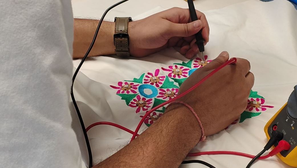
BLE Connect and Neopixel control Testing :
Sound Reactive mode Testing : Unmute the video for the sound / function verification.
Machine Embroidery
As the Embroidery work is involved in my final project, I chose to explore the digital embroidery process for my this weeks assignment.
Workflow : Hand Sketching (PNG) --> Fusion (DXF) --> 2D Design (SVG) --> Inkscape --> INK/Stitch (PES) --> BROTHER SE2000
BROTHER SE2000
Our Lab has Brother SE2000 Embroidery and Stitching Machine.
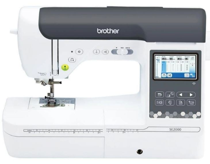
Below are some key details about the BROTHER SE2000 Machine:
| Specification | Details |
|---|---|
| Embroidery Area | Maximum embroidery area of 5" × 7" (18 × 13 cm). |
| Embroidery Speed | Up to 650 stitches per minute for embroidery and 850 stitches per minute for sewing. |
| Display | 3.7" LCD color touchscreen with on-screen editing features, including letter editing, zooming, resizing, rotating, repositioning, and combining embroidery designs. |
| Built-in Content | Includes 193 built-in embroidery designs and 13 built-in embroidery fonts. |
| File Transfer | Supports Wireless LAN (Wi-Fi), allowing embroidery files to be transferred directly from a PC using Design Database Transfer software without requiring a USB drive. |
Embroidery Design Workflow
| Step-by-step | Description |
|---|---|
| Create 2D Design | Prepare your embroidery artwork as an .SVG vector file using Inkscape or another vector graphics editor. |
| Verify Design Size | Check that the design fits within the embroidery hoop size (5" × 7") before exporting. Designs larger than the hoop area may be rejected or clipped by the machine. |
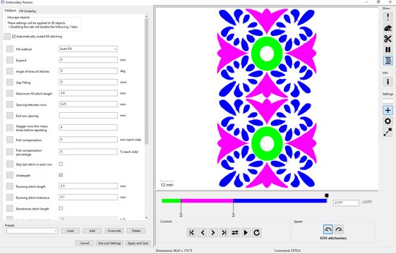
| Digitize the Design | Import the .SVG into embroidery digitizing software such as Brother PE-Design 11, Ink/Stitch, or Embird. I used Ink/Stitch. The software converts the vector artwork into stitch-by-stitch embroidery instructions. |
| Preview the Stitch Path | Use the Ink/Stitch Simulator (or equivalent preview tool) to verify the stitch sequence, or needle path errors before embroidery. |
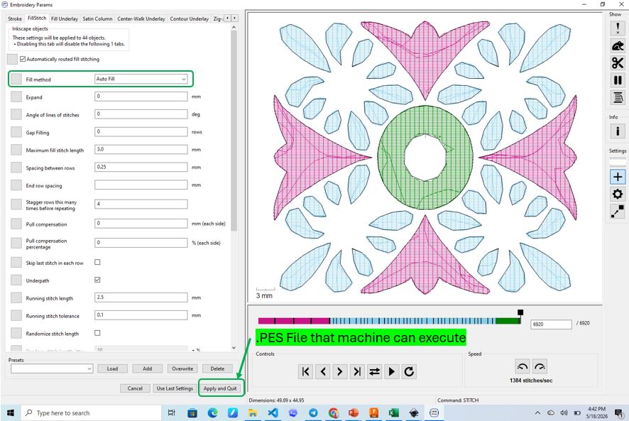
| Export the Design | Export the final embroidery file in the .PES format, which is the native embroidery file format supported by the Brother SE2000. |
| Transfer to the Machine | Transfer the .PES file to the Brother Artspira mobile application. Ensure that both the mobile device and the embroidery machine are connected to the same Wi-Fi network before transferring the design wirelessly. |
Embroidery Design Rules
Before stitching a design on the final garment, it is important to follow a few basic embroidery design rules. These guidelines help improve stitch quality, reduce thread breaks, and prevent wasted fabric and materials.
| Rule | Recommendation | Why It Is Important |
|---|---|---|
| Test Stitch First | Always perform one test stitch on scrap fabric that matches the final garment material. | Embroidery quality, thread tension, and stitch density vary between fabrics such as cotton, satin, silk, and synthetic blends. |
| Stay Within the Hoop Area | Ensure the design fits within the 5" × 7" embroidery hoop before exporting. | Oversized designs may be rejected by the machine or stitched incorrectly. |
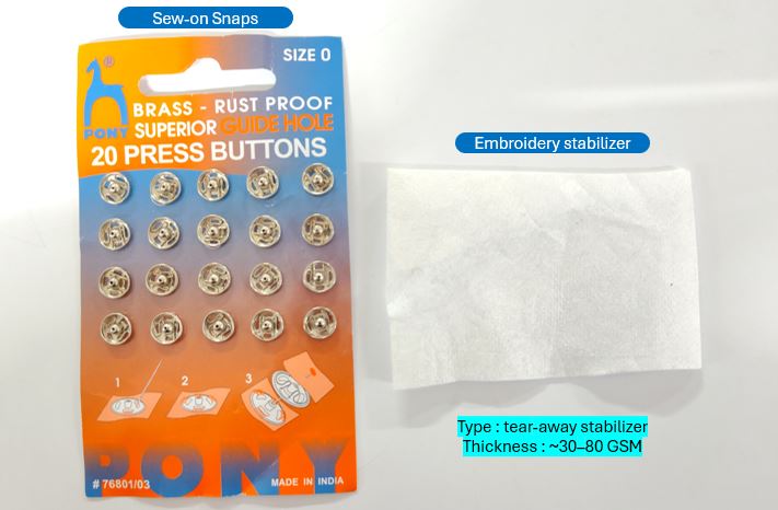
| Choose the Correct Stabilizer | Select an appropriate cut-away, tear-away, or wash-away stabilizer based on the fabric. | Proper stabilization improves stitch quality. |
| Avoid Excessive Stitch Density | Do not place too many stitches in a small area. | High stitch density increases thread breaks, needle heat, and fabric distortion. |
| Use Appropriate Stitch Types | Use Running Stitch for outlines, Satin Stitch for text and borders, and Fill Stitch for large areas. | Each stitch type is optimized for different embroidery features. |
| Check Simulation | Preview the embroidery sequence using the simulator before exporting. | Helps detect travel stitches, overlapping stitches, and stitching errors. |
| Use Quality Thread and Needle | Choose the correct embroidery needle and high-quality embroidery thread. | Reduces thread breaks and improves stitch consistency. |
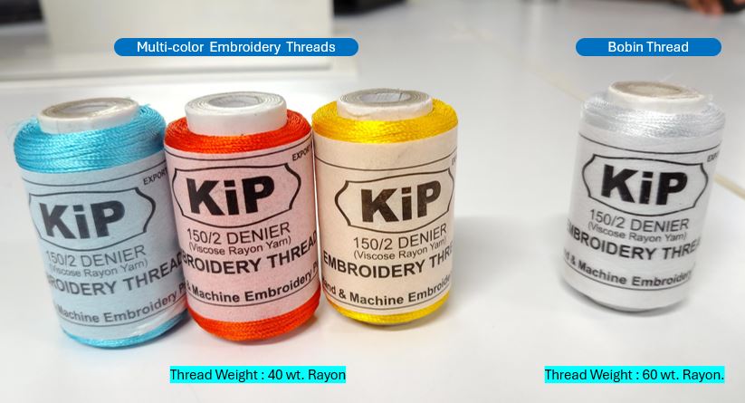
Embroidery Material
I purchased the material from a local shop name Tailor Smart, they have near to industry standard embroidery materials available for DIY embroidery community.
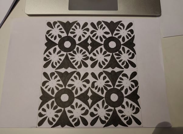
2D Sketching of Embroidery
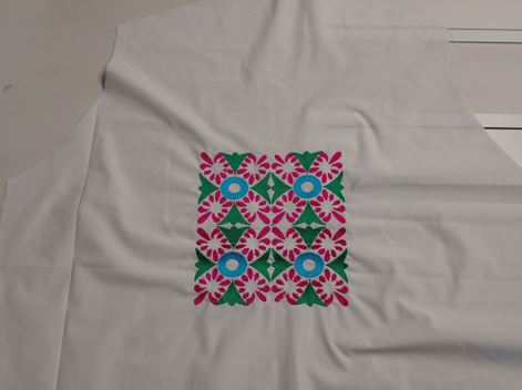
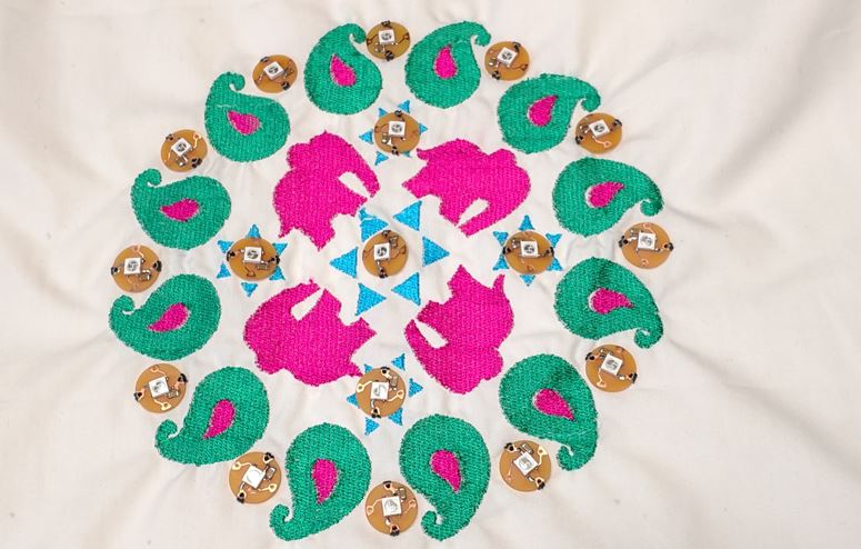
Different regions of India has different Embroidery Styles. I took reference of my mom's embroidery which is done with Rabari Style of Embroidery.

I decided to make two embroidery designs, for one I took reference from my mom's embroidery work. She made one piece of Kutchi embroidery style / Rabari embroidery style work.
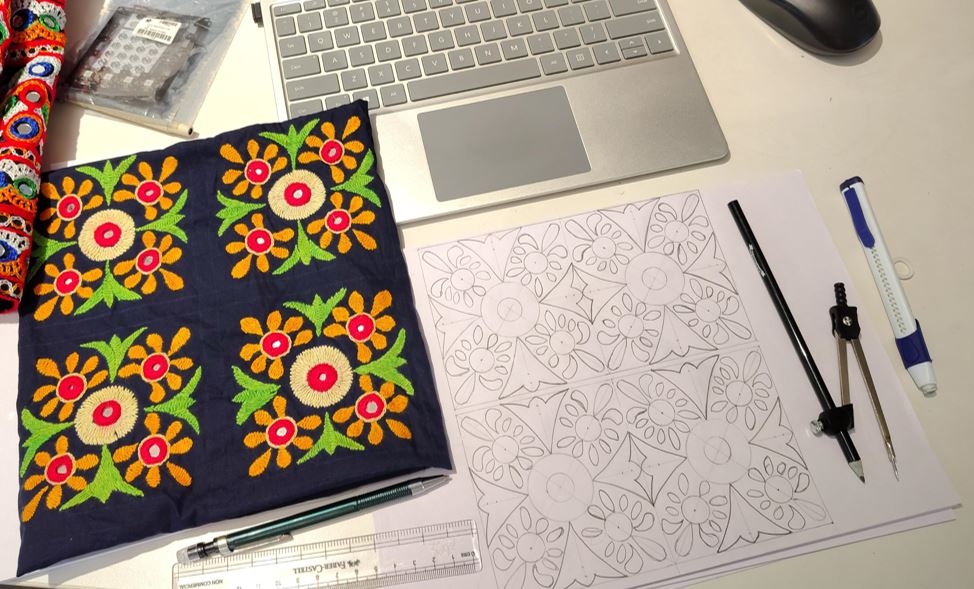
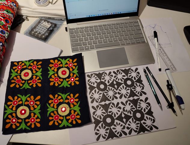
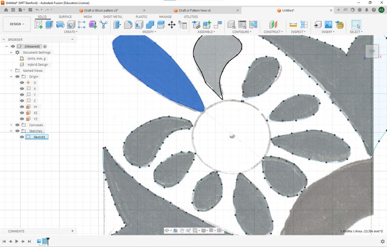
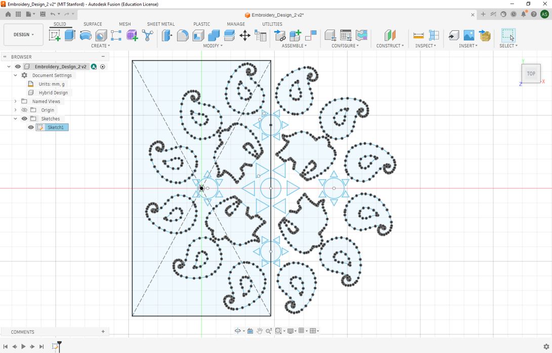
Creating 2D Design Vector file (SVG)
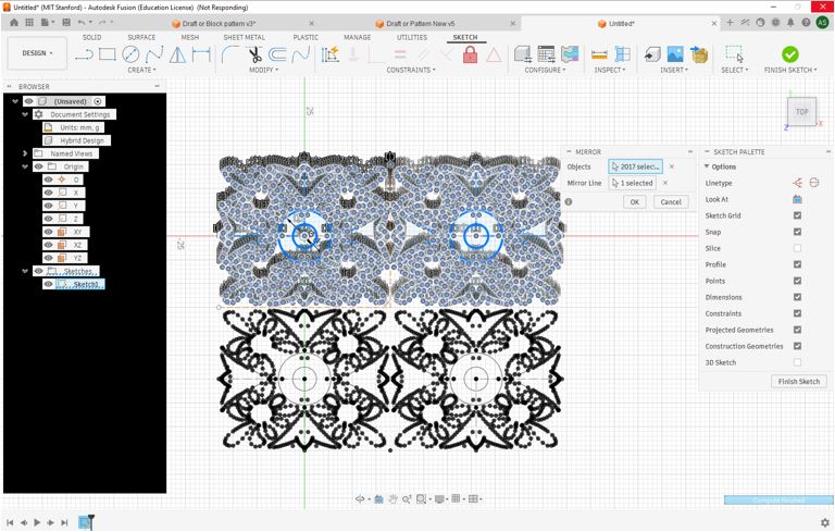
I used Fusion to generate SVG file. First I imported PNG file in to fusion then used Spline tool to drew outlines and finally used mirror tool to multiply the patent.
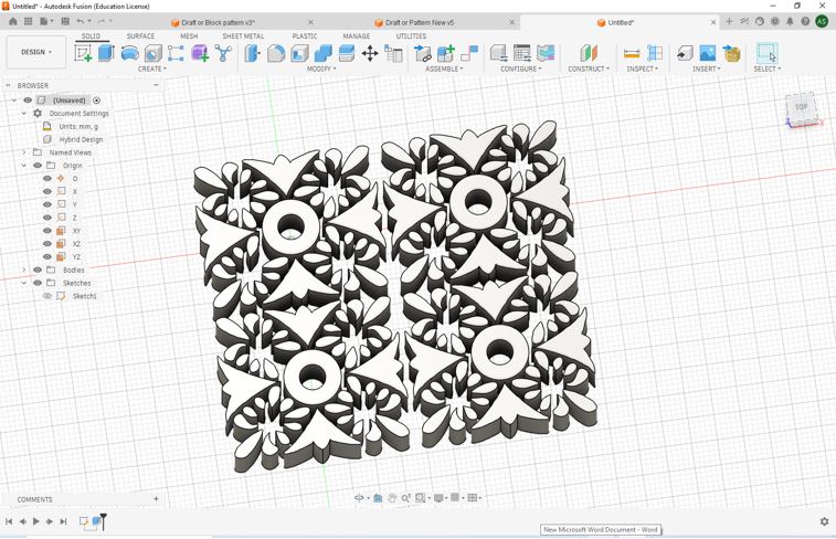
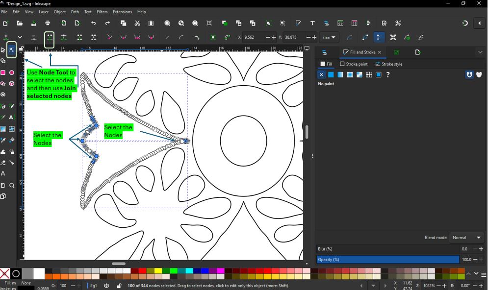
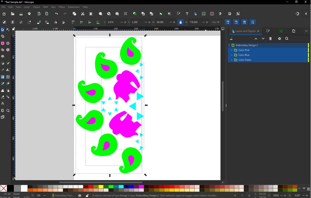
From above file I generated / exported a DXF file and used Concertio.co to convert DXF into SVG. You can download DXF file from here Embroidery_Fusion. Now opened the SVG file into Inkscape. I used Join Selected Nodes to join individual splines. First, Click Node Tool --> Select the two splines --> Select the joining nodes --> Join selected nodes. I need to do this only for splines that are touching the mirror lines.
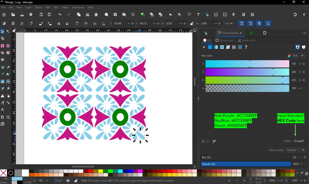
I filled the color using HEX Code values of different colors. Boolean Operation : Select inner circle --> Object --> Raise to top --> Select both circles --> Path --> Difference.
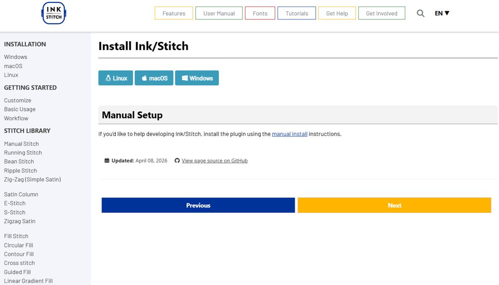
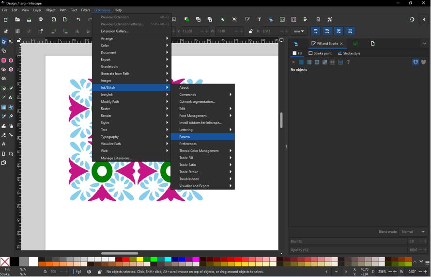
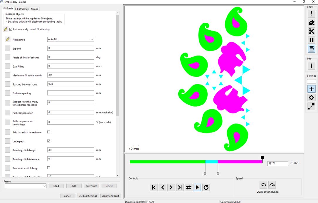
Ink/Stitch Simulator
Download Ink/Stitch Extension for Inkscape. The Ink/Stitch automatically finds the Inkscape extension folder and installs itself.
Transfer (.PES) file to the Machine
I download Brother Artspira Android App for WIFI transfer of .PES file to Embroidery Machine. First, I took the .PES file onto my mobile phone and then opened Artspira App and followed below steps.
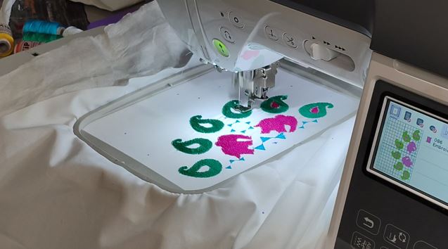
Next is to Load the design and Verify with Trial Function : The Trial function allows you to verify that the embroidery design fits within the fabric and hoop before stitching begins. The machine traces the outer boundary of the design without sewing, helping prevent positioning errors and collisions.
- Load/select the embroidery design and position it on the LCD touchscreen.
- Press the Trial button on-screen icon (as shown in the below video).
- Observe the Boundary - The embroidery carriage will trace the four corners and edges of the design's bounding box without stitching.
- Verify Clearance - Ensure the entire design remains within the fabric area and does not collide with hardware.
- Finally, Begin Embroidery - Once the design position is confirmed, press Start to begin the embroidery process.
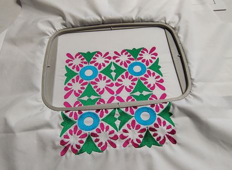
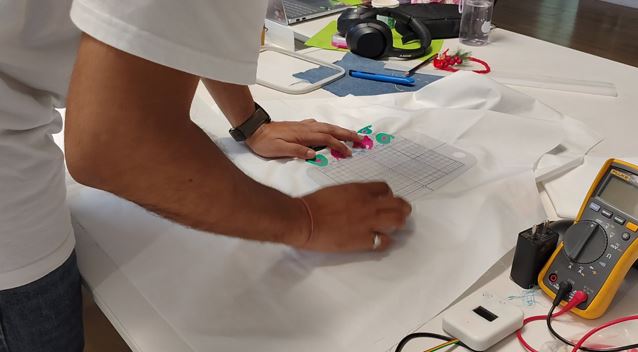
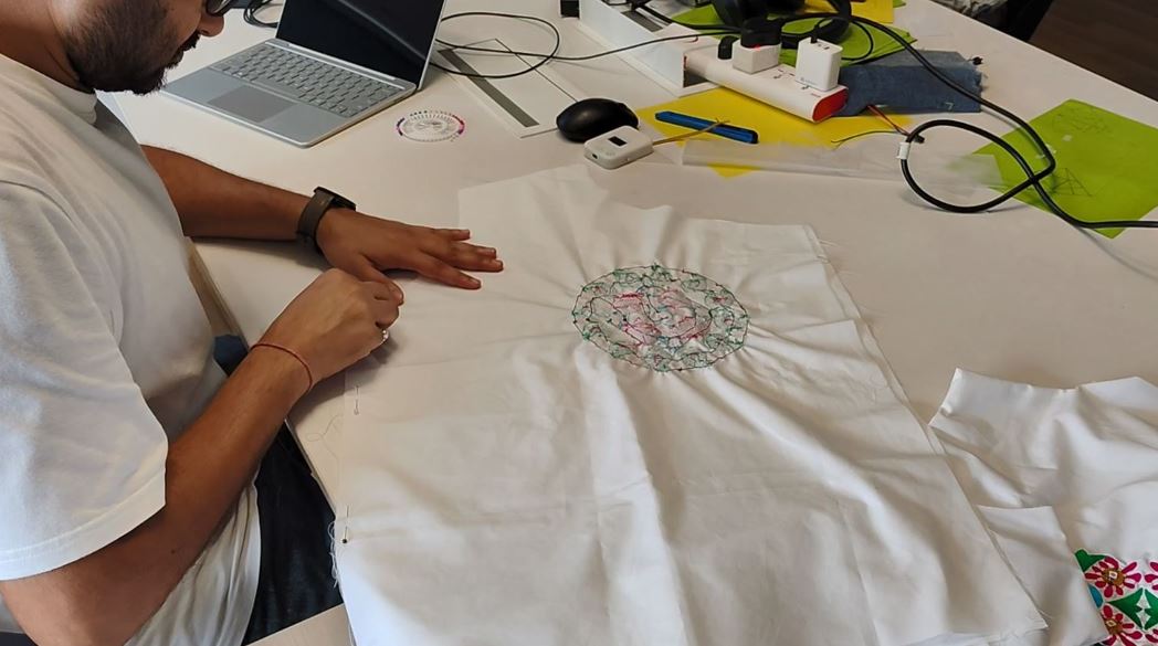
Using the Reference frame to continue the second patch of embroidery in continuation without miss-alignment.

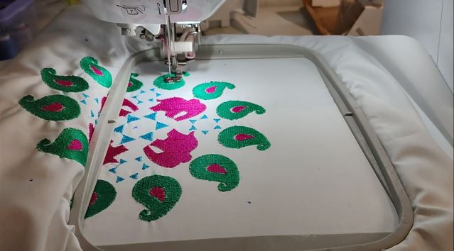
Continuation of Second half of the Embroidery.
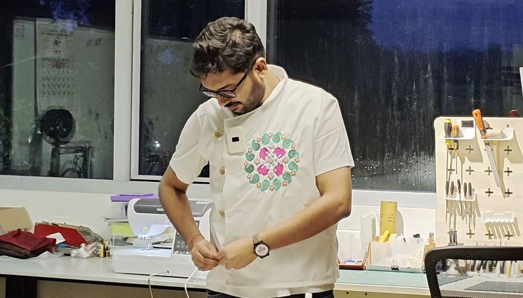
Another Design of Embroidary
I followed the same above explained steps and made the second Embroidery design as follow.
What Went Wrong
The first test run stretched the Fabric it turned created visible gao at the borders of the embroidery. This was even after using filling paper on the back of the fabric.
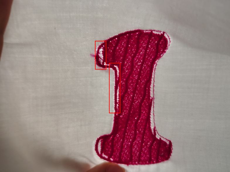
What I Learned
The fabric quality and density matters because the threads of embroidery borders and fill create compression, to withstand this we use lining paper and also the fabric has to have sufficient thickness and density.
Embroidery quality, thread tension, and stitch density vary between fabrics such as cotton, satin, silk, and synthetic blends.
I changed the fabric to a better quality.
With this new thick cotton fabric, I again run a test embroidery to confirm the better embroidery result.

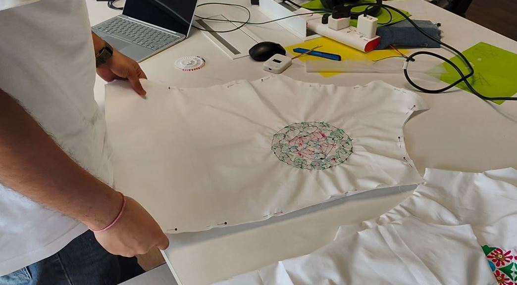
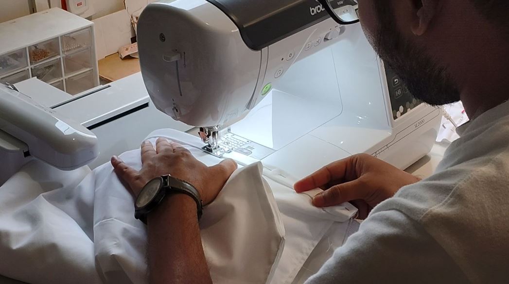
Stitching the Waistcoat
After completing the embroidery and integrating the custom electronic modules, the next step was to assemble the waistcoat. The embroidered front panel was first inspected to ensure that all embroidered motifs were correctly aligned and that the electronic modules were securely attached. The garment panels were then pinned together before performing the final stitching using the Brother SE2000 sewing machine.
During this stage, extra care was taken to avoid stitching over the electronic modules and to leave sufficient clearance for the conductive wiring and future maintenance. The fabric was repeatedly checked for symmetry, fit, and alignment before every seam was sewn.
Inspection before stitching. The completed embroidery was checked for alignment and the custom NeoPixel modules were placed over the embroidered flower motifs to verify their final positions.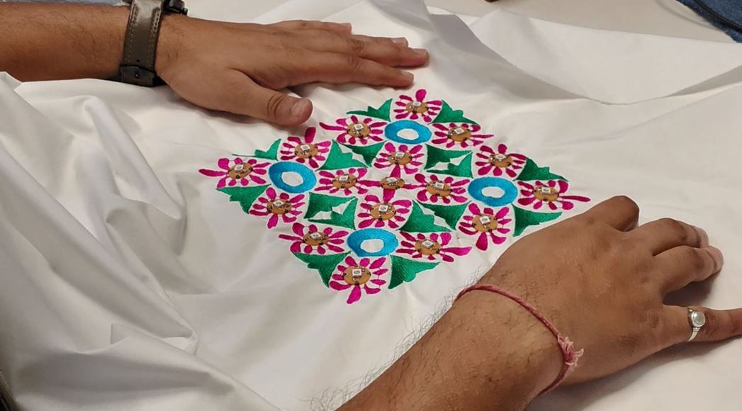
References
- Detailed Steps to add new component to KiCad Library :Snapeda Steps
- Detailed Steps to add Pads in the PCB layout: Ashish Roy Documentation
- Information about using Claude Code Docs
- Expo / User Name :< Abhishek_19